38
Field Wiring
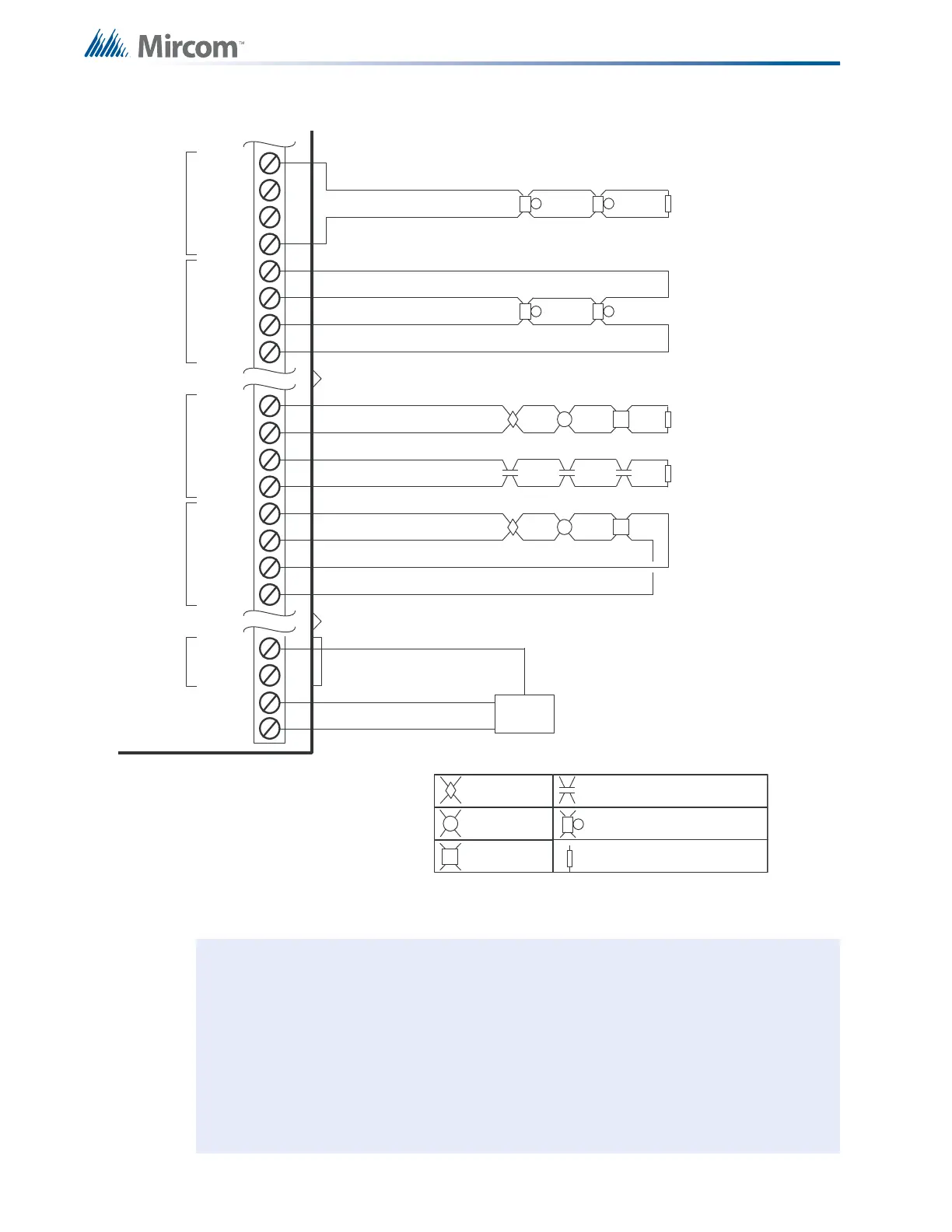
Figure 19 Main Fire Alarm Module Terminal Connections (continued)
Notes: All power limited circuits must use type FPL, FPLR, or FPLP power limited cable.
Initiating circuits are fully supervised and rated for 22 VDC, 3 mA standby, 5 mV
ripple, 50 mA max alarm. They may be configured as required. the alarm
threshold is 21 mA. Maximum loop resistance is 100 ohms; 50 ohms per side.
Indicating circuits are fully supervised and rated for 24 VDC unfiltered 1/7 amp
max. They must be wired as shown in the wiring tables.
To supervise the 24V FWR Aux Power, use an end-of-line relay.
Supervisory or
Waterflow Switch (no)
Bell, horn, or strobe
Heat Detector
Legend: (See LT-1007 for compatible devices.)
Smoke Detector
3.9K 1/2W ELR listed S5434 model
MP-300 manufactured by Mircom
AUXILIARY POWER
FOR ANNUNCIATORS, ETC.
24 VDC UNFILTERED
1.7 AMPS MAXIMUM
-
+
AUX.
POWER
SUPPLY
IND2+ (Z)
IND2- (Z)
IND2- (Y/Z)
SUPERVISED INDICATING CIRCUIT #2
INDICATION
CIRCUIT 1
IND1+ (Z)
STYLE Z
WIRING
IND1- (Y/Z)
IND1+ (Y/Z)
INI1+
INI1-
INI2+
INI2-
INI3+
INI3-
INI4+
INI4-
STYLE D
INI2
STYLE D
INI1
Pull Station
IND2+ (Y/Z)
IND1- (Z)
INDICATION
CIRCUIT 2
INDICATION CIRCUITS 3 & 4
ARE NOT SHOWN
STYLE Y
WIRING
SUPERVISED INDICATING CIRCUIT #1
STYLE B
WIRING
STYLE D NOTE: INITIATING CIRCUITS IN A SERIES 1000
MUST BE ALL EITHER STYLE B OR D.
IF STYLE D IS SELECTED, THE
NUMBER OF CIRCUITS IS CUT IN HALF.
STYLE B
WIRING
STYLE D
WIRING
SUPERVISED INITIATING CIRCUIT #2
(SUPERVISORY OR WATERFLOW ZONE)
SUPERVISED INITIATING CIRCUIT #1
(ALARM ZONE)
SUPERVISED INITIATING CIRCUIT #2
(ALARM ZONE) SEE STYLE D NOTE
INITIATING CIRCUITS 5 TO 8
ARE NOT SHOWN
RTI-1 REMOTE TROUBLE INDICATOR
TRL
TRB

 Loading...


