69
System Configuration
For example, if you wanted Class B operation in a system with eight initiating circuits and four
indicating circuits (main board only), the first six initiating circuits as normal non-verified
alarms, the last two as latching supervisory, and the last indicating circuit as a non-silenceable
strobe, you would use the following sequence:
1. Follow 9.6 Restore to Default/Resize (Class A or B) on page 64.
2. Set Config DIP switch to 0010 0000. All eight initiating yellow trouble LEDs should
illuminate.
3. Set Config DIP switch to 0010 0101. All eight initiating yellow trouble LEDs should go
out.
4. Set the disconnect switches to ON for initiating circuits 7 and 8 only.
5. Press the yellow button for one second. After a pause the yellow trouble LEDs for
initiating circuits 7 and 8 should illuminate.
6. Turn off all disconnect switches.
7. Set Config DIP switch to 0011 0000. All four indicating yellow trouble LEDs should
illuminate.
8. Set Config DIP switch to 0011 0011. All four indicating yellow trouble LEDs should go
out.
9. Set the disconnect switch to ON for indicating circuit four only.
10. Press the yellow button for one second. After a pause the yellow trouble LED for
initiating circuit four should illuminate.
11. Turn off all disconnect switches.
12. Exit configuration mode.
9.10 Configuring Circuit Correlations
As a working definition for correlations, circuits can be defined as:
• input circuits = initiating circuits (detection zones)
• output circuits = indicating circuits (signal zones), and relay circuits
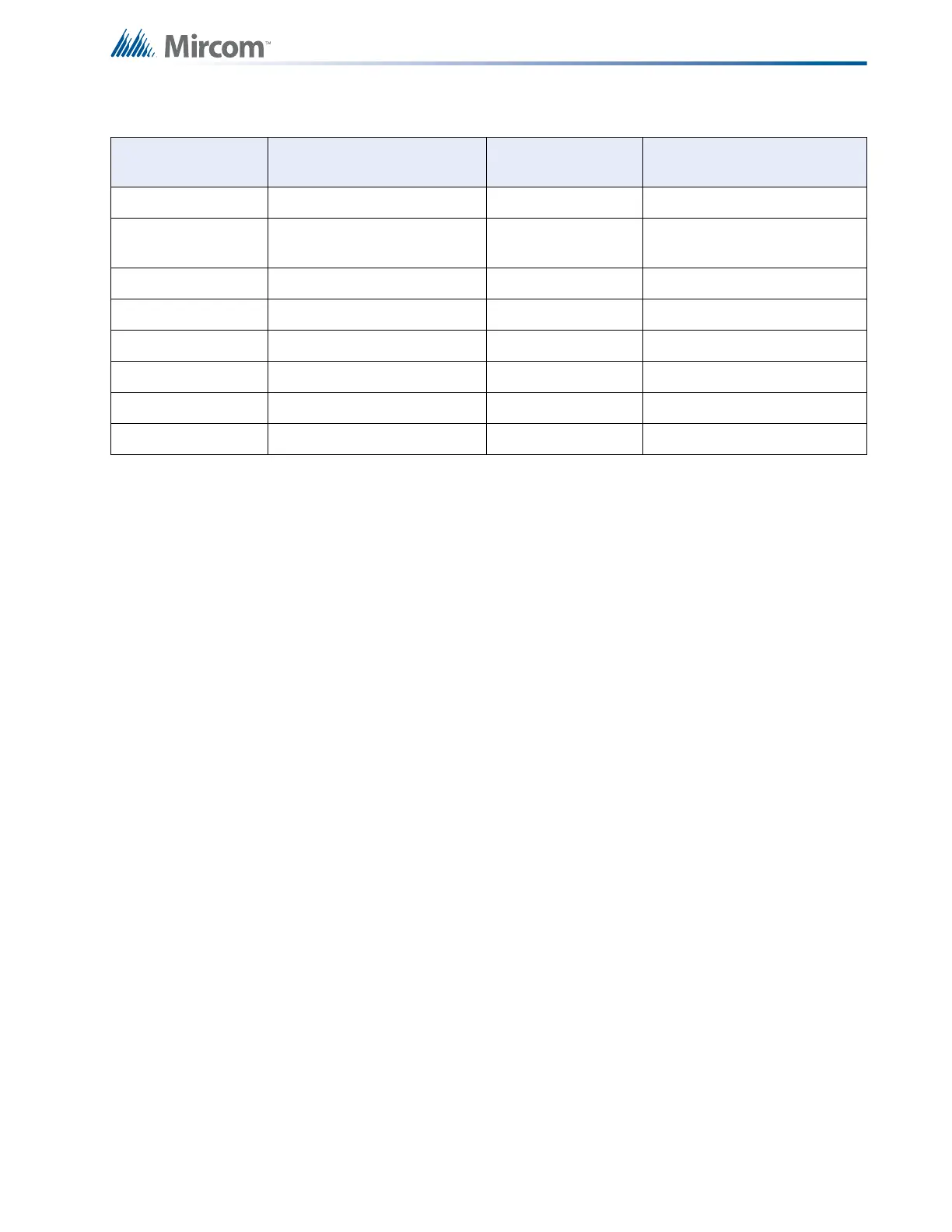
Table 14 Configuring Initiating and Indicating Circuits
Config DIP Switch
Position (1-8)
Initiating Circuit (Detection
Zone) Type
Config DIP Switch
Position (1-8)
Indicating Circuit (Signal
Zone) Type
0010 0000 Normal (Non-Verified Alarm) 0011 0000 Silenceable Audible Signal
0010 0001
Verified Alarm
0011 0001 Non-Silenceable Audible
Signal
0010 0010 Sprinkler Alarm 0011 0010 Silenceable Strobe
0010 0100 Non-Latching Supervisory 0011 0011 Non-Silenceable Strobe
0010 0110 General Alarm
0010 1000 Trouble Only
0010 0101 Latching Supervisory
0010 0111 Property and Building Safety

 Loading...


