34
Module Settings
Jumper JW4 on the main fire alarm panel must be removed if a UDACT-300A is installed.
Please see the UDACT-300A Installation and Operation Manual (LT-888) for more information.
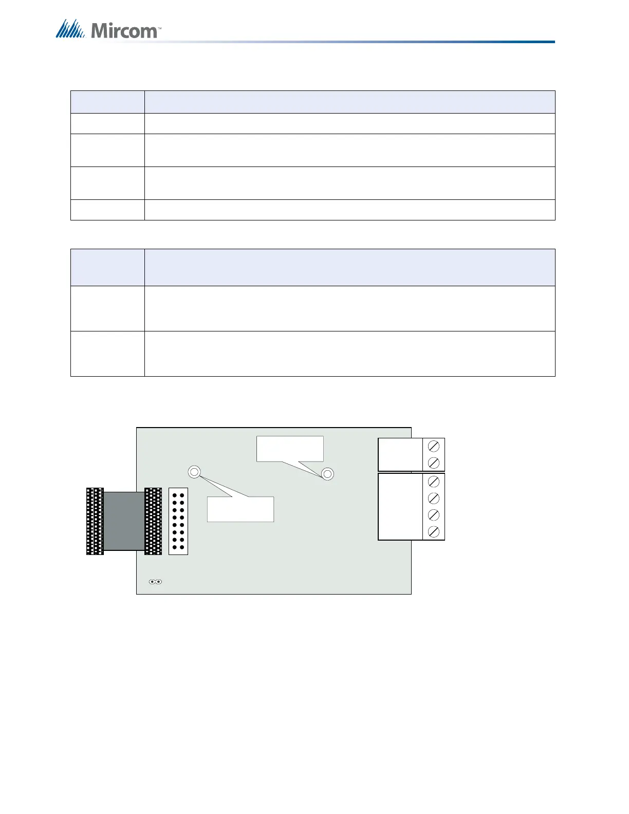
Figure 17 Polarity Reversal and City Tie Module (Model PR-300)
CPU Fail Steady amber for any on board CPU trouble.
Telephone
Line 1
Telephone status indicator LED; Red when the line is in use, Amber when there is a line
trouble.
Telephone
Line 2
Telephone status indicator LED; Red when the line is in use, Amber when there is a line
trouble.
Power ON Green LED is ON steady when power is supplied to the board.
Table 4 Jumpers
JUMPER
NUMBER
JUMPER FUNCTIONS
JW1 Normally open. Place jumper here and power down the UDACT-300A by disconnecting
P1 or power down the fire alarm panel (AC and Batteries), then power back to revert to
default passcode. After reset, remove the jumper. Leave normally open.
JW2 Normally open to BLOCK remote configuration via modem, PC with a UIMA converter
module or using the LCD and keypad at the UDACT-300A. Place jumper here to ALLOW
any type of configuration. Remove jumper once configuration is complete.
Table 3 UDACT-300A List of LEDs and their Functions (Continued)
POLARITY
REVERSAL
ALARM
POLARITY
REVERSAL
SUPV
CITY
TIE
+ | - + | - + | -
JW4
P1 P2
Mounting hole for
#6-32 screws
Mounting hole for
#6-32 screws