63
System Configuration
9.3 Entering Configuration Mode
The system enters configuration mode whenever any of the configuration DIP switches 2 to 8
(switch 1 is used to enter walk test mode) are set to a "1" or the ON position (top position). The
Test / Config Mode and Common Trouble LEDs will turn on and the buzzer will sound. You can
silence the buzzer at this point.
If there is no activity (no buttons pressed or switches changed) for one hour, the system will
return to normal operation, but will remain in a trouble condition.
As you change the configuration DIP switches to select different functions, wait for a few
seconds for the appropriate LEDs to change as the system recognizes the change(s). Note
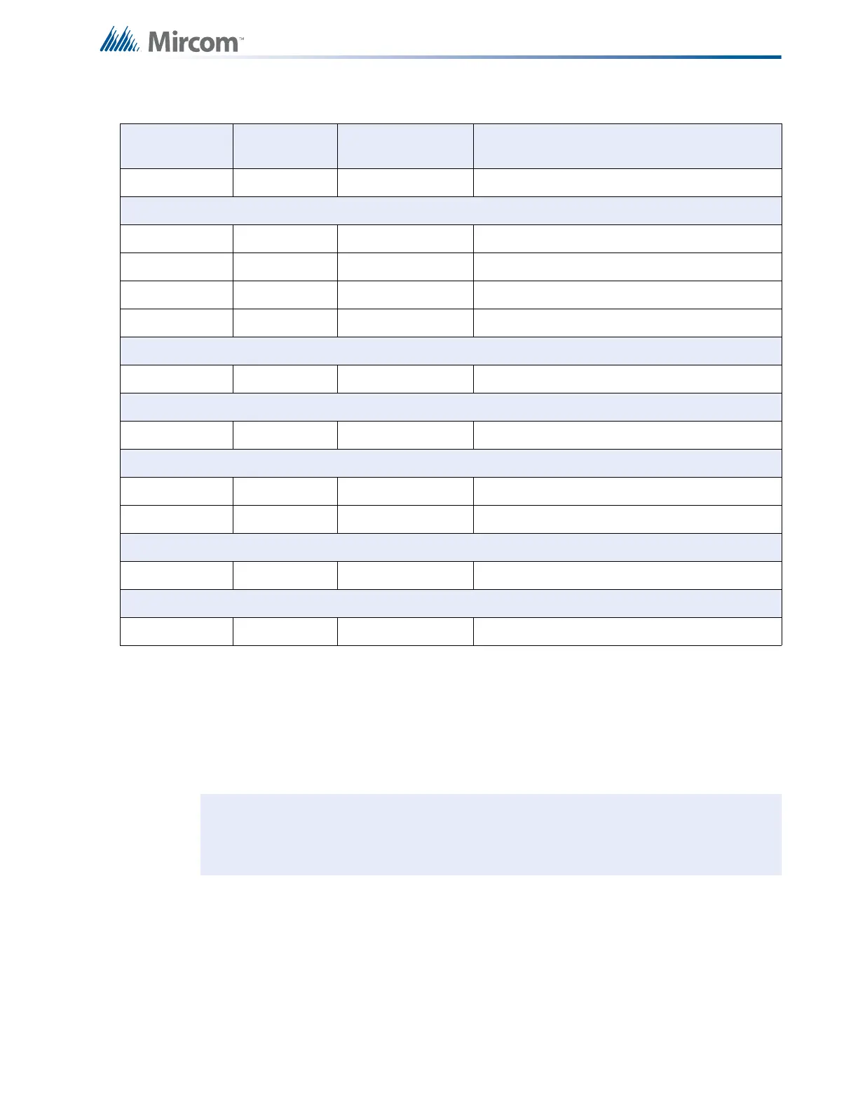
0010 1000 28 Yellow Trouble Only
Indicating Circuits/Signal Zones
0011 0000 30 Yellow Silenceable
0011 0001 31 Yellow Non-Silenceable
0011 0010 32 Yellow Silenceable Strobes
0011 0011 33 Yellow Non-Silenceable Strobes
Relays
0011 1000 38 None Show Relay Circuits
Resize System
0100 0000 40 Yellow and Red Set Circuit Adder Module Number and Type
Correlations
0100 0001 41 Yellow Correlation by Input Circuit
0100 0010 42 Yellow Correlation by Output Circuit
Default
0111 1111 7F Yellow and Red Restore to Default Configuration
Walk Test
1000 0000 80 None Walk Test
Note: The fire alarm control panel is not operating as a fire alarm system while it is in
configuration mode.
Table 12 Configuration DIP Switch Functions (Continued)
DIP Switch
Position (1-8)
Function
Number
Button
Operations
Description
 Loading...


