68
System Configuration
9.9 Configuring Initiating and Indicating Circuits
Initiating circuits (detection zones) and indicating circuits (signal zones) are configured by
using the configuration DIP switches to select the desired circuit type function, along with the
circuit trouble LEDs and disconnect DIP switches.
To configure initiating and indicating circuits
1. Select a circuit type by raising the specified DIP switch(es) (see the table below). The
yellow trouble LED for each circuit currently configured as that type will illuminate.
2. To configure circuits to be of that selected circuit type, turn on all of the desired circuit
disconnect DIP switches (up position) and press the yellow button for about one second.
After a short pause, the initiating circuit yellow trouble LEDs will be updated to show the
new configuration.
3. Lower all DIP switches to the OFF position and press the System Reset button.
0000 1111 PR-300/DACT alarm
Transmit Silence
Option
An illuminated yellow LED indicates that the alarm transmit
signal from the PR-300 or DACT will be silenceable with the
activation of the signal silence button. If the yellow LED is off
(default), it indicates that the alarm transmit signal from the
PR-300 or DACT will not be silenceable.
0001 0000 AC Power Fail Delay
Time
The AC Power Fail trouble signal from the PR-300 or the
DACT can be delayed when the only trouble on the fire alarm
panel is AC power fail.
Yellow LED flashes 0 times = No Delay (default)
Yellow LED flashes 1 time = 1 Hour
Yellow LED flashes 2 times = 2 Hours
Yellow LED flashes 3 times = 3 Hours
Notes: Any subsequent selection of a particular circuit as a different circuit type will
supercede the previous selection. Also note that the physical circuit type must be
appropriate for the selected circuit type. For example, only indicating circuits can
be configured as silenceable strobes.
Be sure to reset circuit disconnect switches to OFF (down position) before
attempting to configure any other circuits.
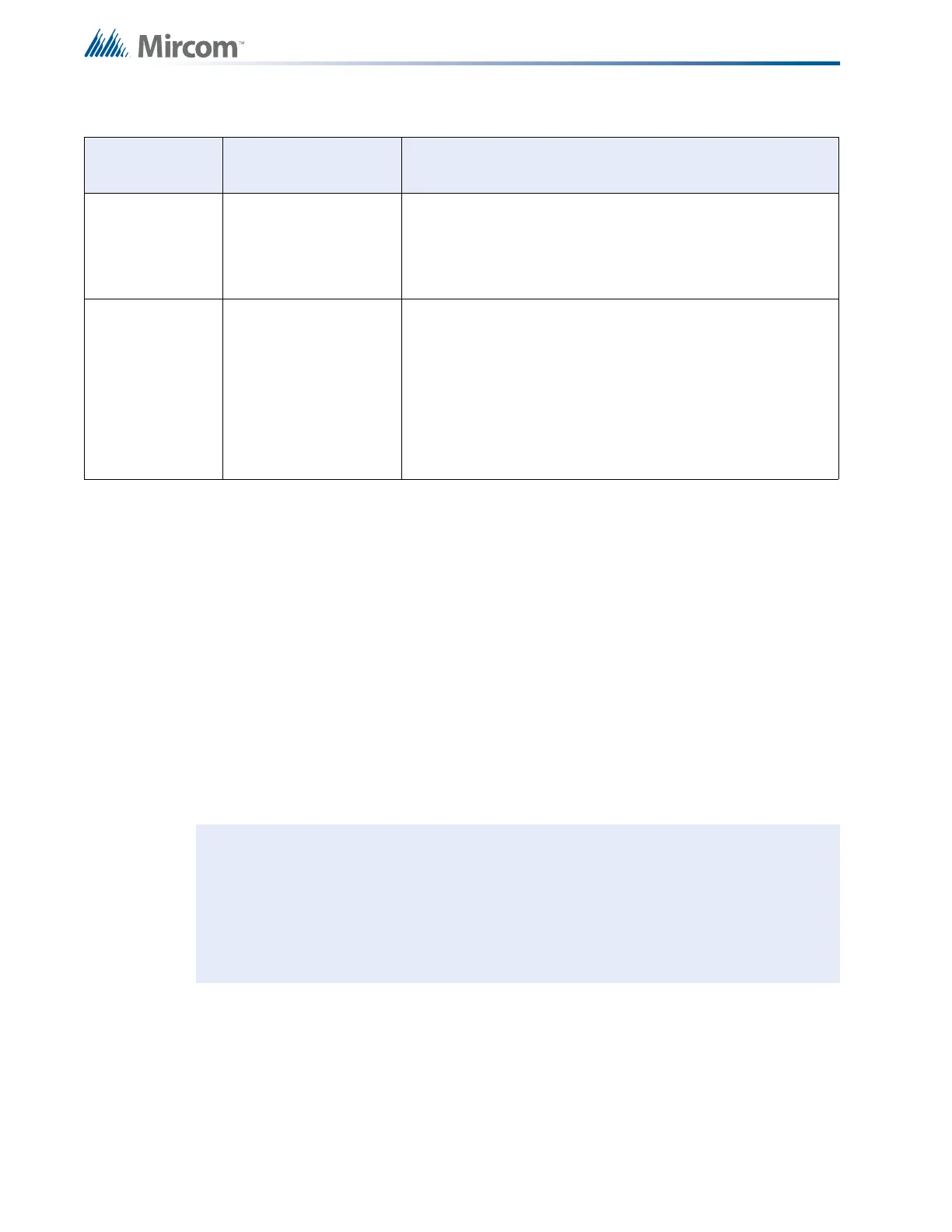
Table 13 Configuration Features (Continued)
DIP Switch
Position (1-8)
Features Description

 Loading...


