67
System Configuration
0001 0010 Signal Circuit Isolator
Option
An illuminated yellow LED indicates that if a short circuit
exists on any indicating circuit and an alarm condition
follows, then those indicating circuits will be activated
anyway. If the yellow LED is off (default), then under the
same conditions, the indicating circuits will not be activated
to prevent wasting power. This feature is needed when signal
isolator devices are employed so that indicating circuits will
be activated even under shorted conditions.
0011 1000 Show Relay Circuits All display points assigned to relay circuits will be lit.
0000 1010 Signal Silence Inhibit
Timer
Yellow LED does not flash = Disabled (default)
Yellow LED flashes 1 time = 1 minute (ULC required)
Yellow LED flashes 2 times = 2 minutes
Yellow LED flashes 3 times = 3 minutes
0000 1011 Auto Signal Silence
timer
(This timer cannot be
set shorter than either
the Auto General
Alarm or Signal
Silence Inhibit timers, if
those timers are
enabled)
For Canadian
installations, disable
the Auto Signal Silence
timer.
Yellow LED does not flash = Disabled (default)
Yellow LED flashes 1 time = 5 minute
Yellow LED flashes 2 times = 10 minutes
Yellow LED flashes 3 times = 15 minutes
Yellow LED flashes 4 times = 20 minutes
Yellow LED flashes 5 times = 30 minutes
0000 1100 Auto General Alarm
Timer
(Leave disabled unless
the system is
configured for Two
Stage operation)
Yellow LED does not flash = Disabled (default)
Yellow LED flashes 1 time = 5 minute
Yellow LED flashes 2 times = 10 minutes
Yellow LED flashes 3 times = 15 minutes
Yellow LED flashes 4 times = 20 minutes
Yellow LED flashes 5 times = 30 minutes
0000 1101 Audible Indicating
Circuit Evacuation
Code
Yellow LED flashes 1 time = Continuous
Yellow LED flashes 2 times = March Time
Yellow LED flashes 3 times = Temporal Code (default) (UL &
ULC required)
Yellow LED flashes 4 times = California Code
0000 1110 Number of Remote
Annunciators
The yellow LED flashes 0 to 8 times to indicate the number of
remote annunciators expected by the system. (default 0
flashes)
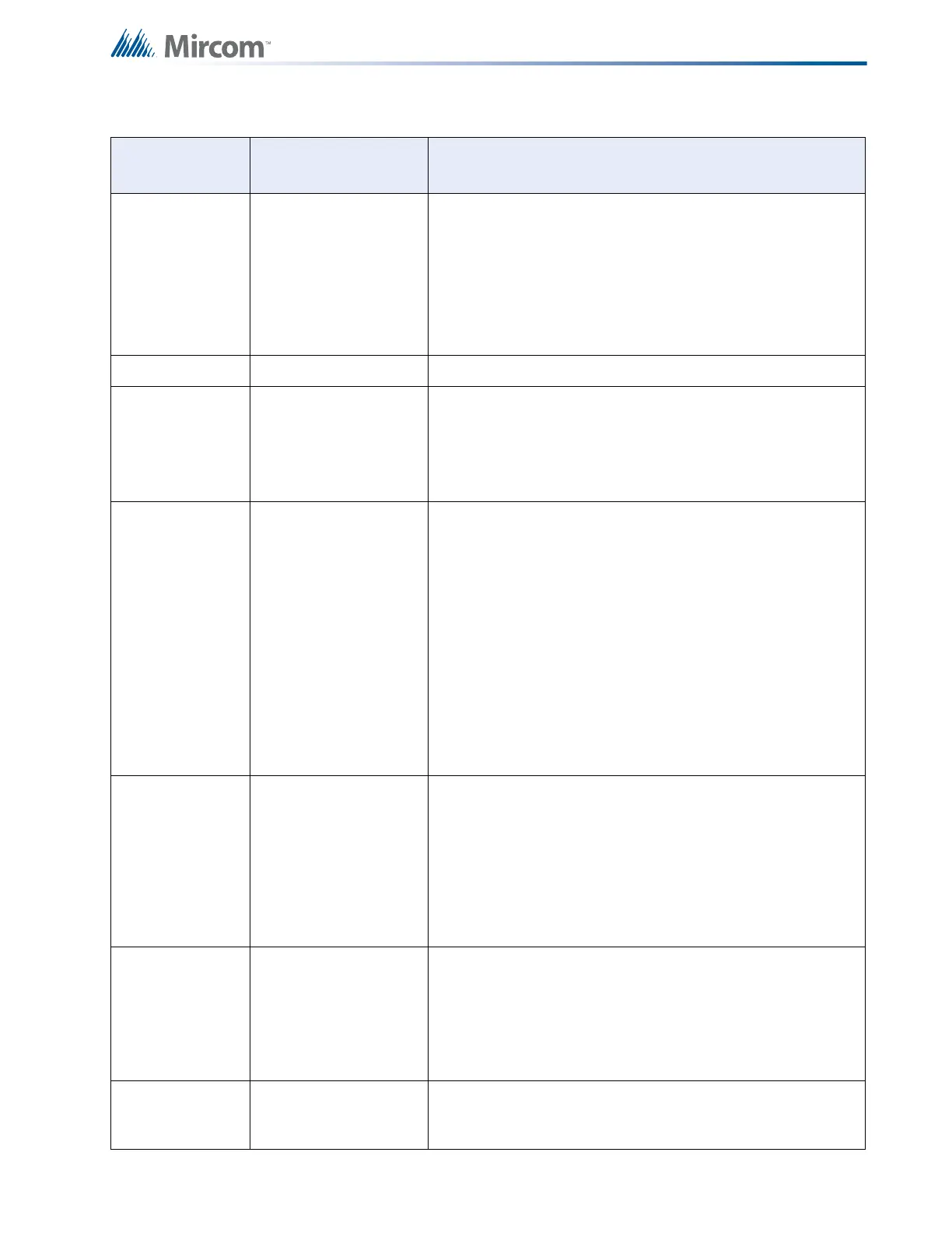
Table 13 Configuration Features (Continued)
DIP Switch
Position (1-8)
Features Description

 Loading...


