27
Module Settings
5.2.1 Connectors
The main display module provides four dedicated display points for the four indicating circuits
on the main fire alarm module. It also provides the following general-purpose display points:
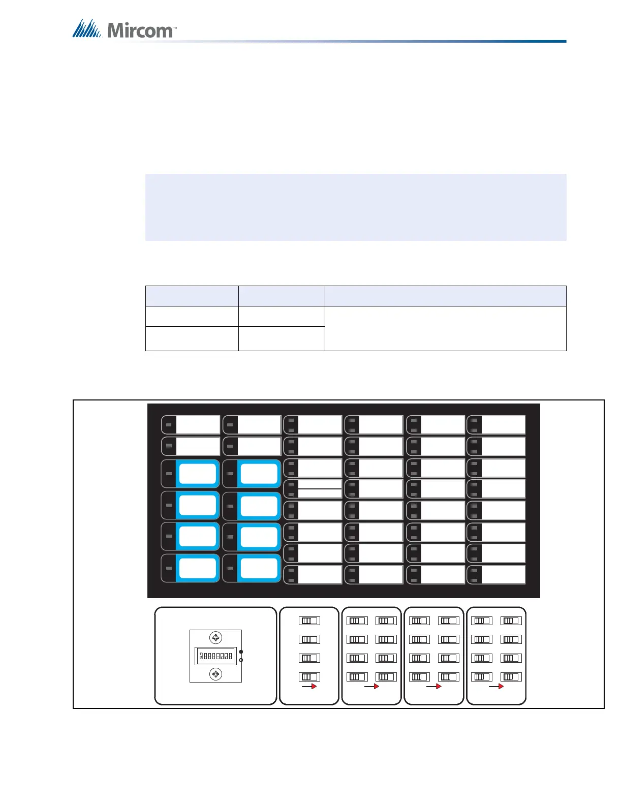
On the MCC-1024-6S and MCC-1024-12S Chassis for the U.S.A. market only, the main
display module is shown in Figure 11, below. The Disconnect DIP-switches are replaced by
slide switches.
Figure 11 Main Display Module (MCC-1024-6S, MCC-1024-12S)
P1 Cable connects to P3 of main fire alarm module.
P2 Connection to P1 of ECH-1048 display Module if used.
SW1 to
SW5
See 9.0 System Configuration on page 60 and 8.0 Indicators, Controls, and
Operation on page 49.
Note: The main display module comes with a Label Sheet (NP-2854) including both
English and French slide-in labels. This sheet may be run through a laser printer
for labelling purposes before being installed. The first slide-in section comes in
two versions; one for single-stage systems, and one for two-stage systems.
Chassis Type Display Points
MCC-1024-6 24 The main display has dedicated display points for
the eight initiating circuits and four indicating
circuits that are located on the main board.
MCC-1024-12 24
CONFIGURATION
1 8
DISCONNECT
POINT/ZONE
1
26
5
37
48
POINT/ZONE
DISCONNECT
DETECTION ZONE
DISCONNECT
SIGNAL ZONE
DISCONNECT
4
3
2
1
3
48
7
1
2
5
6
3
48
7
1
2
5
6
CONFIGURATION
1 8
DISCONNECT
POINT/ZONE
1
26
5
37
48
POINT/ZONE
DISCONNECT
DETECTION ZONE
DISCONNECT
SIGNAL ZONE
DISCONNECT
4
3
2
1
3
48
7
1
2
5
6
3
48
7
1
2
5
6
COMMON
1
ZONE
2
ZONE
3
ZONE
4
ZONE
5
ZONE
6
ZONE
7
ZONE
8
ALARM
SUPERVISORY
COMMON
REMOTE
FAILURE
TEST/CONFIG
MODE
SYSTEM
RESET
FIRE
DRILL
GENERAL
ALARM
COMMON
TROUBLE
A.C.
ON
LAMP
TEST
AUXILIARY
DISCONNECT
SIGNAL
SILENCE
CPU FAULT
GROUND FAULT
SIGNAL 1
TROUBLE
SIGNAL 2
TROUBLE
SIGNAL 3
TROUBLE
SIGNAL 4
TROUBLE
ZONE
BATTERY/
CHARGER
TROUBLE
AUTOMATIC
ALARM SIGNAL
CANCEL
ALM/SUP/TBL/
BLDG AUDIBLE
SIL

 Loading...


