15
System Components
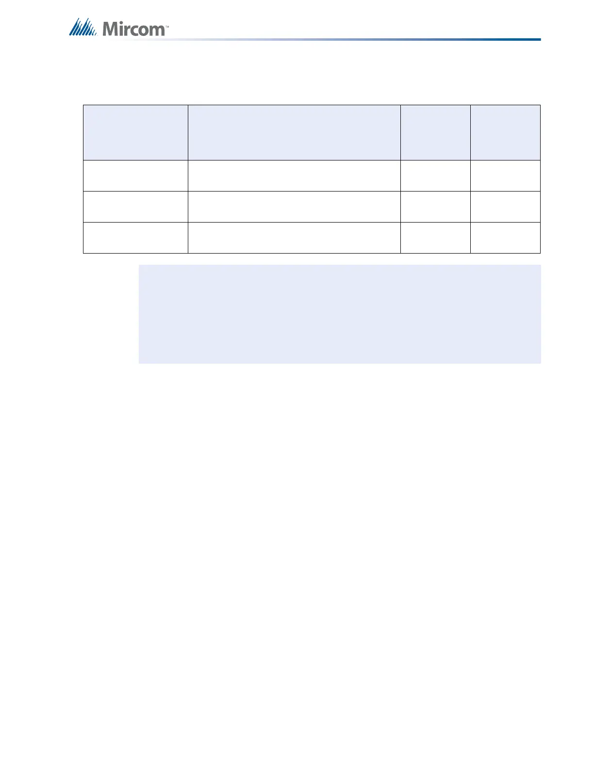
The "S" Version Chassis have slide switches instead of DIP switches for disconnects. The
maximum number of each circuit adder module type is outlined in the following table.
Module Description Maximum Total per
System
DM-1008A
Eight detection circuit modules (total of 64
initiating circuits in a system).
764
SGM-1004A
Four signal circuit modules (total of 24 initiating
circuits in a system).
316
RM-1008A
Eight relay circuit modules (total of 32 relay
circuits in a system).
432
Notes: Any FA-1000 System may have a PR-300 or UDACT-300A and up to eight (8)
Remote Multiplex Annunciators externally. As good practice, it is recommended
that circuit adder modules be installed in the order of detection modules, followed
by signal modules, followed by relay modules.
All systems can carry a maximum of eight adder modules in the combinations
permitted above.

 Loading...


