SECTION
MITL91
OS/91
lo-096-350-NA
line for maintenance purposes, the switches should be set-to
8888.
:
.:
I..._.
.I-
,.
.
:.
(:
:
(b) Load Functions: The Customer Program Dump/Load Function
requires the switches to be set to 5523 to initiate a load from
an external storage device.
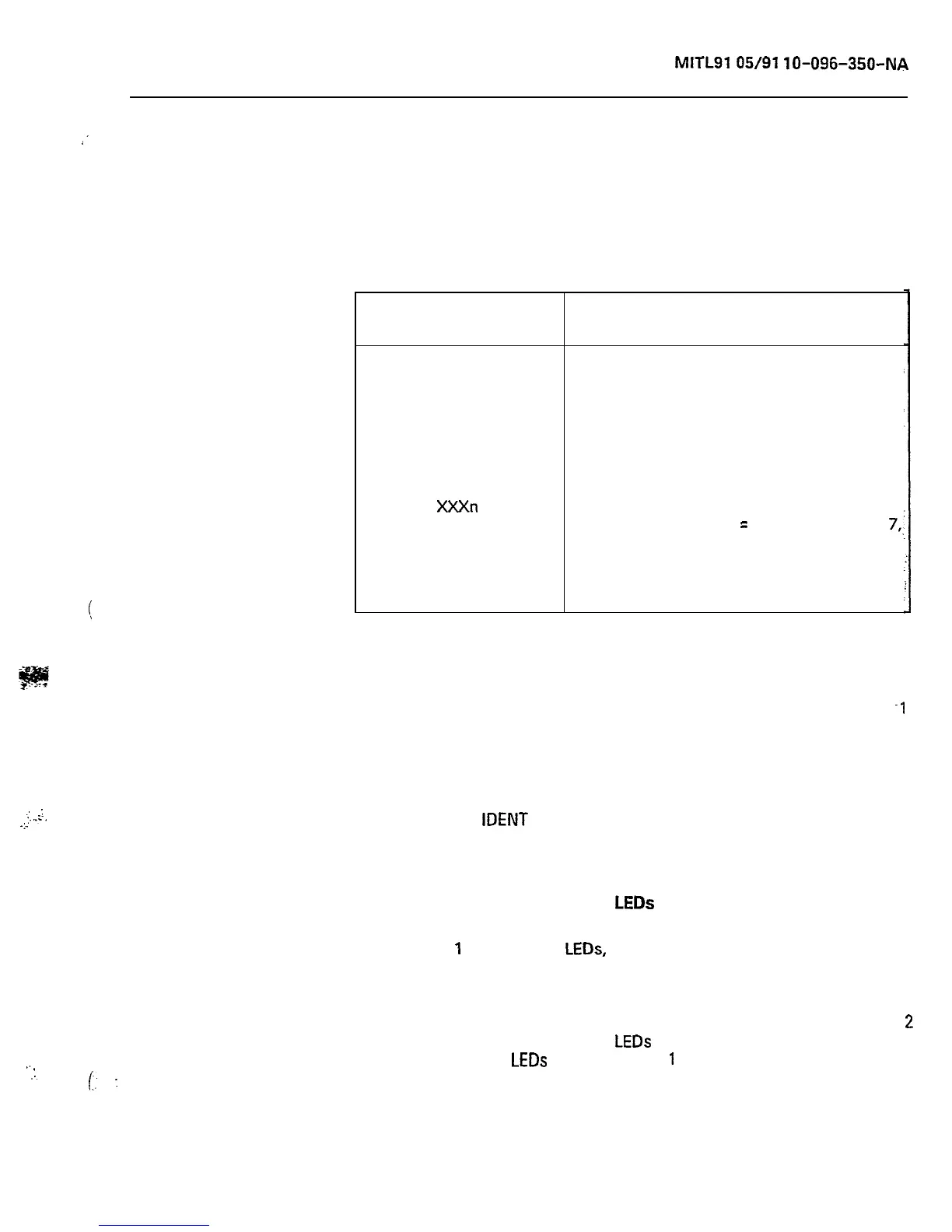
TABLE 2-2
SWITCH SETTINGS
Switch
Settings
7770
7771
7772
7776
XXXn
777n
5623
Function
Enter Maintenance Console into
programming mode
Enter Supervisor Console 1 into
programming mode
Enter Supervisor Console 2 into
programming mode
Initialize System Configuration (Clear
RAM)
Take any console out of programming
mode (one of the X
=
any digit except
7,,
n = O-9)
Enables reset from test line (n = O-2);
Dial 555-6
Load Function
Console Control Card (Basic)
2.12 The console control card provides the interface between the
system and two consoles. Console control card number
-1
(position 17) is allocated to the maintenance console connector and
the Supervisor console number 1 connector. Console control card
number 2 (position 16) is allocated to the Supervisor console number 2
connector. The card provides both voice and data signals to and from
each console (see Figure 2-2). To identify the console, the operator
may press the
IDENT
button. The last segment in the DESTINATION
Display identifies the console as 0 for maintenance, 1 for console 1, or
2 for console 2.
Console Control Line and Data
LEDs
2.13 LINE
1
and LINE 2
LEDs,
when lit, indicate that the associated
console is active (i.e., the handset or headset is plugged in). The
designations 1 and 2 refer to the two consoles handled by the card.
The maintenance console will appear in slot 17, line 2. Console 1 will
appear in slot 17, line 1. Console 2 will appear in slot 16, line 1. Line.
2
in slot 16 is not used. The data
LEDs
indicate voice pair continuity to
the console(s). The
LEDs
labeled DATA
1
and DATA 2 flicker whenever
data is transmitted from the corresponding console to the console
control card (data is transmitted when any console button is pressed).
Page 9