ment numbers and speech path number being used. The date will
appear in the time display.
Error Codes
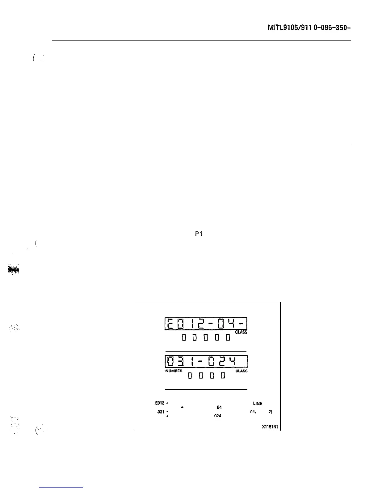
3.06 Table 4-4 is a list of error codes displayed on the console,
indicating the card causing the malfunction and the type of
malfunction. Figure 3-2 shows a typical error display and its inter-
pretation.
Power Fail Transfer Switch
3.07 This switch (on the underside of the console), when in the
TRANSFER position, manually switches the system into power
fail transfer (unless the appropriate power fail transfer enable switch
on the maintenance panel is in the DISABLE postion). Operation of the
switch from the NORMAL to the TRANSFER position will cause all
existing calls on the transferred trunks to be released, and the MAJOR
alarm LED will light. The switch should only be operated in emergency
situations. For normal operation, the switch should be in the NORMAL
position.
Test Line Functions
3.08
The test line is on equipment number 001, and appears both on
and on terminal posts on the maintenance panel.
It must be programmed to be an extension, and should have full trunk
access for use by maintenance personnel.
3.09
As well as its normal facilities as an extension, certain addi-
tional features exist exclusively for the test line. These are the
ability to: directly access a trunk: set and clear the busy-out con-
ditions of speech paths and receivers; clear all errors and busy-out
conditions in the system (except for trunks); and select a specific
NUMBER
CIASS
DunllD
ATT INT RCL DID MAN
SOURCE
ATT RING BUSY ERR
DESTINATION
EOlZ
-
UNABLE TO CONNECT A SPEECH PATH TO
LINE
CARD
IN 04
-
CARD POSITION
04
SHELF
1
031
-
EQUIPMENT NUMBER 31 (SHELF 1
CARD
04,
UNIT
7j
024
-
SPEECH PATH TO USE
024
XllSlRl
Figure 3-2 Typical Readout