SECTION
MITL9105/91
lo-096-350-NA
l
Appendix H
-
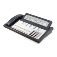
gives a brief description of the SUPERSET 4 set,
including physical characteristics and electrical and
environ-
(+--
:
mental specifications.
l
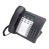
Appendix I
-
gives a brief description of the SUPERSET 3 set,
including physical characteristics.
Reason for Reissue
1.02 This Section has been reissued to include additional UCD
(Uniform Call Distribution) information.
1.03
It should be noted that certain sections and appendices must
be used as interlocking information for complete troubleshoot-
ing.
The
SUPERSET
3 and
SUPERSET
4 Sets
1.04
For test information on the
SUPERSET
3 set or the
SUPERSET
4
set, see Section MITLS 105/g 11
O-096-320-NA.
For Engineering
Information on the
SUPERSET
4 set, see Section
MITL9105/9110-096-
180-NA.
Basic Troubleshooting Philosophy
1.05 The SX-lOO/SX-200 system employs automatic diagnostics
which, in most cases, can pinpoint faults to a specific printed
circuit card. A system malfunction is generally corrected by the re-
placement of an indicated faulty circuit card with a known (good)
spare. Should the need arise, the actual shelf backplane or power
supply may be easily replaced by a new unit. The tables,
MAPS
and
explanations in this Practice should be sufficient in most ‘cases to
cover any problems which may arise in the field.
’
1.06
Actual field repair of components on cards, shelves or power
supplies is never done. All defective units should be returned to
MITEL, as per Section MlTL9105/911
O-096-200-NA.
2. CIRCUIT CARD AND MAINTENANCE PANEL AIDS
2.01
The SX-lOO/SX-200 system is equipped with various main-
tenance aids that will be of assistance to the repair person
troubleshooting the system. This Part is a card-by-card description
with specific reference to all indicators, switches and fuses on the
cards. In addition, the connectors and switches on the maintenance
panel are also described.
Card Shelf
.
.
2.02
Figure 2-l illustrates the card locations in the equipment shelf
or shelves. A visual display of all cards is shown in Figures 2-2,
2-3(a) and 2-3(b). Fuses on the backplane of the shelf are described in
\
paragraph 2.25.
Page 2