SECTION MITL91 OS/91 1
O-096-350-NA
:*
I
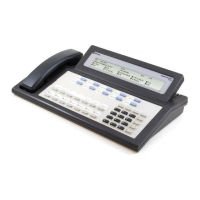
(b) Console (CON) Alarm LED: The Console Alarm LED flashes to
c-
indicate a console malfunction. The LED will go off when the
alarm has been cleared or canceled.
(c) Major (MAJ) Alarm LED: The LED turns ON to indicate that a
malfunction has occurred which has caused the power fail
transfer relays to operate:
0
When the MAJ Alarm LED is ON, the system is automatically in
Power Fail Transfer mode.
l
Typical examples of major alarms include Scanner failure or
CPU malfunction, Power Supply voltages out-of-tolerance.
l
The MAJ Alarm LED, unlike the other console
LEDs,
is hardwired
from the system cabinet to the console.
0
A colon in the time display indicates that the console is receiv-
ing power and the handset is plugged in.
0
A time display indicates that the system and console proces-
sors are running. It also indicates that the link from the console
control card to the console is correct. (Note: If cable is not in
correctly, time will flash or will be incomplete.)
ALARM RESET Button
3.03 This button is used to reset the flashing MIN Alarm LED and the
audible signal associated with the alarm indication. When the
button is pressed it:
l
Resets the flashing LED to steady and extinguish the audible
alarm signal associated with the alarm condition.
0
Displays in the SOURCE and DESTINATION fields, details of the
alarm condition, including the location of the printed circuit
card that has malfunctioned.
3.04
A typical alarm readout in the SOURCE display is shown in
Figure 3-2. In addition, if the ALARM RESET button is pressed,
the Busy Lamp Field changes to display lines and trunks which are
locked out or have been busied-out This display remains for as long
as the ALARM RESET button is held down.
IDENT
Button
3.05
If the
IDENT
button is pressed when the console is idle, the
SOURCE display will show the installed firmware generic num-
ber, and its revision. The DESTlNATlON display shows an internal firm-
ware code and the number of the console at which the key was
pressed (see Figure 3-3). If the
IDENT
button is pressed when the
i’
Y
Supervisor is connected to either a source or destination party, the
SOURCE and DESTINATION displays will change to show the
equip-
Page 22