LED FLASHING (by switch on card
(b) Trunk Incoming and Outgoing Busy Switches: Associated
with each trunk circuit are two busy switches: one for making
the trunk busy outgoing and one for making the trunk busy
incoming. Table 2-3 lists the switch settings and describes their
effect.
Standard Line Card
2.17
The Line card contains eight separate line circuits. The line
circuit detects on- and off-hook conditions, which are recog-
nized by the scanner and reported to the processor for appropriate
action. Dial signals (rotary dial or DTMF) are passed over the speech
path selected for the conversation (see Figure 2-2). The LED on each
line circuit provides an indication that the line circuit has detected an
off-hook condition. The LED is driven directly from the off-hook detect
circuit in the line circuit. It turns ON when an off-hook condition is
detected and will flash when dial pulses are sent.
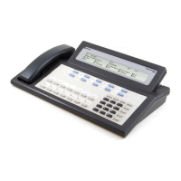
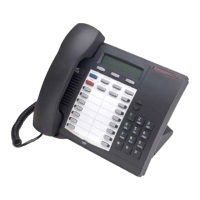
The
SUPERSET
Line Card
2.18 The
SUPERSET
3 set or the
SUPERSET
4 set requires a
SET Line card that is not compatible with standard telephone
sets. The card contains eight separate line circuits with eight
indicating on-/off-hook conditions. The line circuits act as interfaces
sets and the system CPU (Central Processor
Unit). The system processor continually polls all line circuits to deter-
mine calls for service, time updates, messaging, etc. No actual dial
signals are sent between the
SUPERSET
3 set or the
SUPERSET
and the system, as all communication is digitally sent. For further
information, see Section
MITL91
OS/91
10-096-l 80-NA.
RAC
2.19
The Recorded Announcement Card (RAC) occupies one periph-
eral slot in the system and provides two different 8 second
recordings using digital solid-state storage. Messages are recorded on
the Supervisor’s console. If required, the two 8 second messages may
be linked to provide one 16 second message. In the front faceplate of
the card there are eight DIP switches. The first four switches may be
used to busy out a particular channel (two channels per recording).
The fifth and seventh switches are the write-protect switches. These
switches may be set to disable recording. In addition there are four
indicator
LEDs
(one per channel) that are lit when a channel is
out or in use.
Maintenance Panel
2.20
At the top of the equipment cabinet -is the maintenance panel
(Figure 2-4). This panel provides the service personnel with
access to the system through the maintenance console connector and
test line terminals. Also housed on the maintenance panel are the six