SECTION
MITL9105/911
O-096-350-NA
TABLE 2-3
L
:
OUTGOING/INCOMING SWITCH SETTINGS
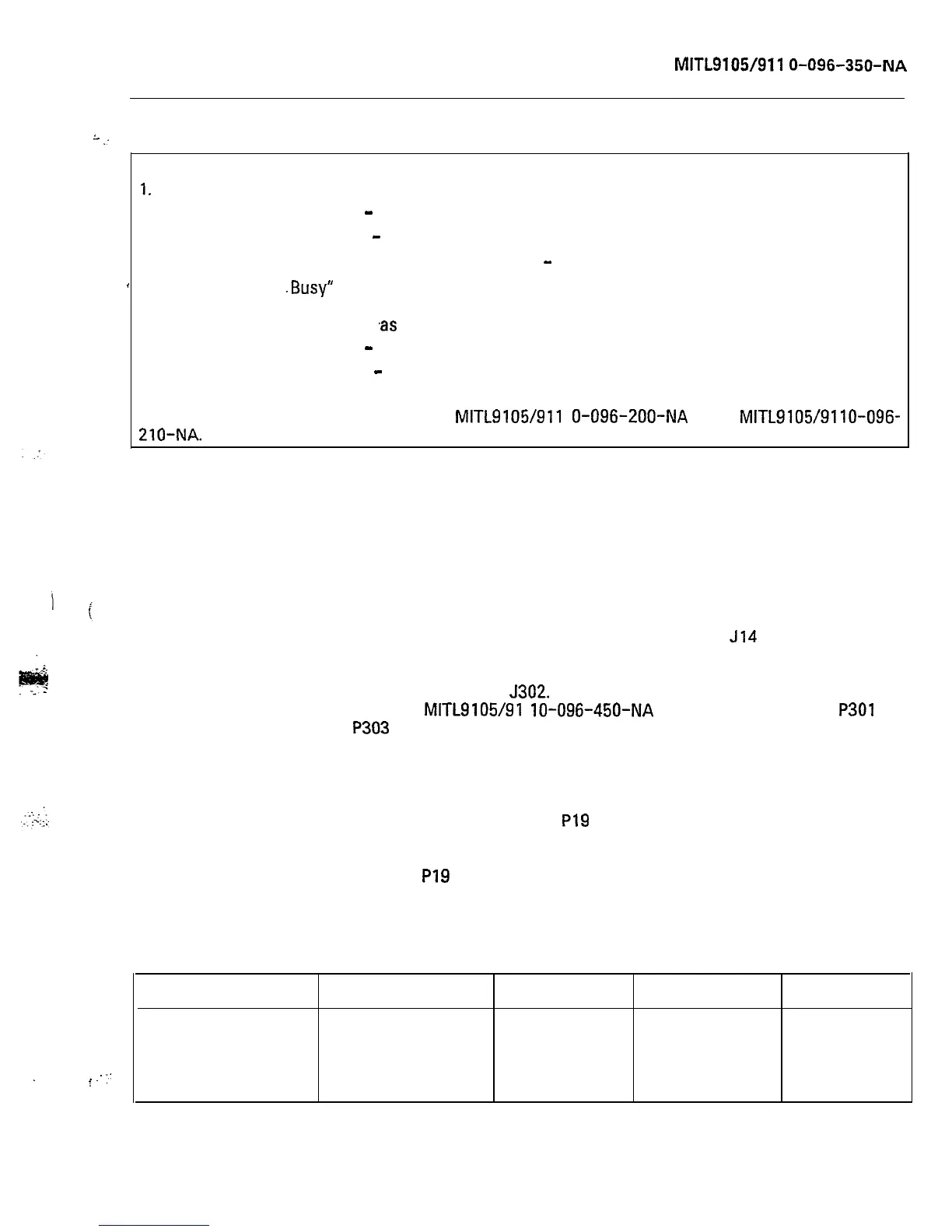
Trunk Busy Switches:
1.
Outgoing busy switches (one per trunk) can be set for either of the following conditions:
ldle Setting
-
Normal trunk operation.
Busy Setting
-
Trunk cannot be seized for outgoing call.
If the switches are not set in this manner, “Ring
-
Don’t Answer”, may occur.
’
2. The “Outgoing
.Busy”
condition may be set either by the outgoing busy switch, or by the
console ‘Trunk Busy-Out” function. When this condition is in effect, the incoming busy switch
affects the trunk condition
‘as
follows:
Idle Setting
-
No answer will be given to incoming CO calls.
Busy Setting
-
A permanent seizure condition is given towards the CO when
the trunk is seized for the first line.
For further information, see Sections
MITL9105/911
O-096-200-NA
and
MITLg105/9110-096-
210-NA.
Cards External to the Shelf
2.21
There are a number of cards that are external to the equipment
shelf (shelves). These cards, and the system they are part of,
are listed in Table 2-4.
.
f
-.
:’
The SX-200 Interconnect Card
2.22 The SX-200 Interconnect Card (Figure 2-5) provides a direct
connection between the consoles (J13,
J14
and J15) and the
shelf backplane (P16 and P17). This board also contains the console
fuse for protection of the console. Directly opposite the fuse is the
RS-232 printer port
J302.
For a complete description of this port, see
Section
MITL9105/91
lo-096-450-NA
and Table 2-5. Plugs
P301
and
P303
are the maintenance panel connector and the power supply
out-of-tolerance monitor, respectively. All power for the Interconnect
card is supplied through the power supply terminal block TB301 on the
board. Plugs J13, J14 and J15 are the console plugs. Plugs P16 and P17
provide interconnection between the Interconnect card and the shelf
backplane. Plugs P18 and P19 provide a connection between the Inter-
connect card and the Cross-Connect Field. P18 carries Night Bell Con-
tacts, Music on Hold, Tip and Ring for RMATS and Paging access
circuitry. P19 carries Tips and Rings for the
card
shelf slots 13 and 14.
TABLE
2-4
EXTERNAL SYSTEM CARDS
Card
Interconnect
Power Fail Transfer
Console Interface
sx-200
Figure
sx-100
Figure
1
card
2-5
1 card 2-8
1
card
2-6
combined
1
card
(or
2,
2-7
sx-200)
Page 13