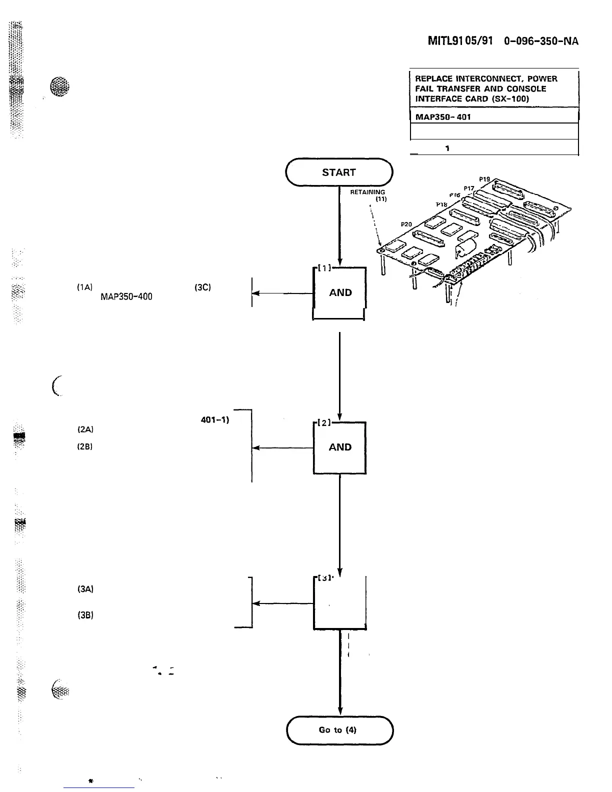
(1A)
Complete Steps (1) to
(3C)
of
MAP350-400
4
Sheet
1
of 4
SCREWS
(11)
6-b
\
SECTION
MITL91
OS/91
1
O-096-350-NA
Issue 3. Mav 1984
I
I
POWER TERMINAL
BLOCKS
EXPOSE SYSTEM
x1591
Figure 401-l
Interconnect Card
AT TOP OF SYSTEM (FIGURE
401-l)
(2A)
Remove P16, P17 and the
maintenance panel connector
(28)
Remove power cables from the
power terminal blocks. Also
remove reserve battery backup
connection
(3A)
Remove the eleven 3-16 in.
screws that secure the
interconnect card to the chassis
(38)
Remove the Interconnect card
REMOVE CABLESREMOVE CABLES
AND
1
REMOVE
INTERCONNECTINTERCONNECT
CARD
Page D-11
m
.,
..
 Loading...