;;:\;
.:a:..‘
.:i.,
,.,:>:,
:,i;?,:
SECTION
MITL91
OS/91
lo-096-350-NA
.:.,::::
,.,.
:.
‘.
,I
:
~:.
CONVERTER INPUT LED
,
DC/DC CONVERTER
?
1
POWER IS
CONTROLLED BY
SVSTEM POWER
NIGHT
BELL
-4av
NIGHT
BELL
FUSE
d
b
TB2.5
TB2.4
.
-
0
-
TB2.1 Tf32.3
I
OPTIONAL
RESERVE
BATTERY
AC
POWER
LED
175
v a A
sL0
f3Lo
CIRCUIT
BREAKER
x1473
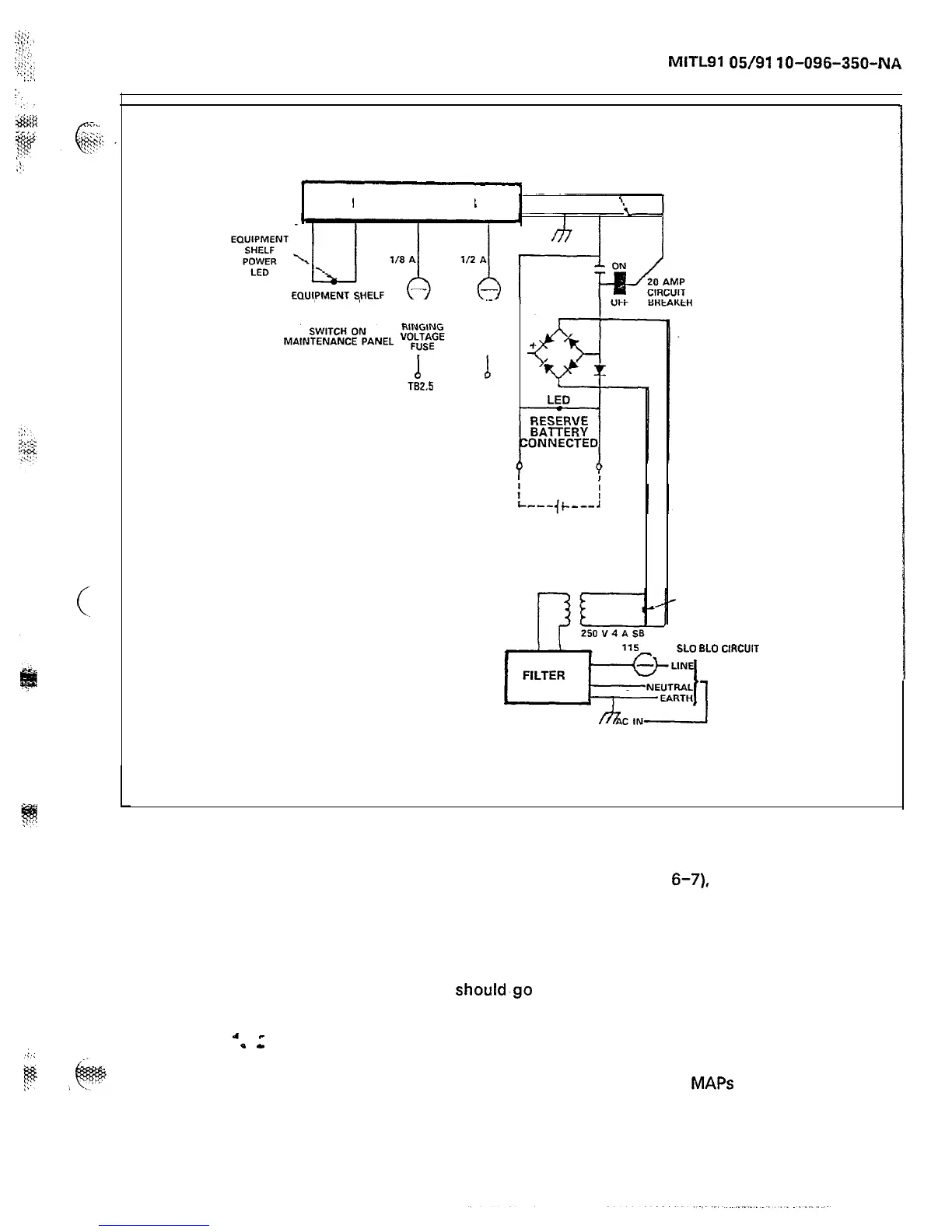
Figure 6-4 SX-200 Back Door Electrical Schematic
6.08 When troubleshooting the systems for power failures, the Pow-
er Supply Block Diagram (Figure
6-7),
and Charts 6-l through
6-10 should be consulted. The charts outlined cover the trouble and its
effect on the system. In most cases the repair person will be directed
to a specific MAP for remedial action. Under the heading “Check”, a yes
answer to the question asked is an indication to go on to the next
question in the “Check” column. If a no answer is encountered, the
repair person should.go to the “Action” column and follow the instruc-
tions listed there. There is also a column indicating (by an X) to which
system the action applies. Above all, it must be remembered that fuse
replacement is not a remedy. The probable cause of a power failure
should be determined before the system is powered-up. Utilizing the
information provided in this Section and the MAPS referred to in Charts
Page 77