42
4 CONNECTING THE SERVO AMPLIFIER AND ROTARY SERVO MOTOR
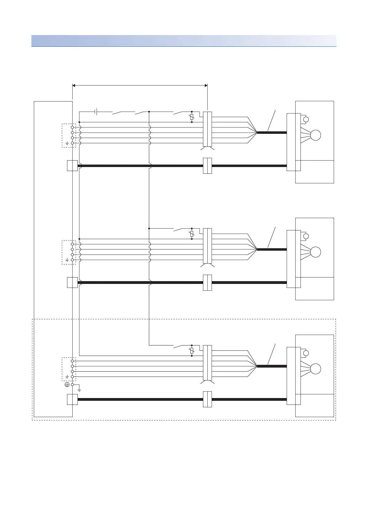
4.2 Wiring
Connection diagram 11
Fabricate an extension cable as shown below.
Refer to the following for the wires used for the extension cable.
Page 55 Selection example of wires
*1 Configure a circuit which interlocks with an emergency stop switch to shut off.
*2 The electromagnetic brake terminals (B1 and B2) have no polarity.
*3 Do not use the 24 V DC interface power supply for the electromagnetic brake.
*4 Connect a surge absorber as close to the rotary servo motor as possible.
*5 For MR-AEKCBL_M-_, refer to the following.
Page 80 MR-AEKCBL_M-_
*6 This connection is for the MR-J5 3-axis servo amplifier.
CN2A
CNP3A
MR-AEPB2J10CBL03M-A1-L
MR-AEPB2J10CBL03M-A2-L
MR-AEPB2J10CBL03M-A5-L
MR-AEPB2J10CBL03M-A1-L
MR-AEPB2J10CBL03M-A2-L
MR-AEPB2J10CBL03M-A5-L
MR-AEPB2J10CBL03M-A1-L
MR-AEPB2J10CBL03M-A2-L
MR-AEPB2J10CBL03M-A5-L
*4
U
V
W
B
M
U
MBR-A
CALM
CN2B
CNP3B
*4
U
V
W
B
M
U
MBR-B
CN2C
CNP3C
*4
U
V
W
B
M
U
MBR-C
*1
MR-AEKCBL_M-L
*5
MR-AEKCBL_M-H
*5
MR-AEKCBL_M-L
*5
MR-AEKCBL_M-H
*5
MR-AEKCBL_M-L
*5
MR-AEKCBL_M-H
*5
*6
50 m or shorter
Extension cable
Rotary servo motor
Servo amplifier
24 V DC power
supply for
electromagnetic
brake
*3
(Electromagnetic brake
interlock for A-axis)
(AND malfunction)
B1 (yellow)
*2
Electromagnetic
brake
B2 (brown)
U (red)
V (white)
W (black)
E (green/yellow)
Junction connector
for extension cable
Junction connector
for motor power cable
Encoder
Rotary servo motor
(Electromagnetic brake
interlock for B-axis)
B1 (yellow)
*2
Electromagnetic
brake
B2 (brown)
U (red)
V (white)
W (black)
E (green/yellow)
Junction connector
for extension cable
Junction connector
for motor power cable
Encoder
Rotary servo motor
(Electromagnetic brake
interlock for C-axis)
B1 (yellow)
*2
Electromagnetic
brake
B2 (brown)
U (red)
V (white)
W (black)
E (green/yellow)
Junction connector
for motor power cable
Junction connector
for extension cable
Encoder
 Loading...


