4G1 ENGINE (E–W) – Alternator and Ignition System
11A-3-1b
PWEE9520
E
Nov. 1995Mitsubishi Motors Corporation
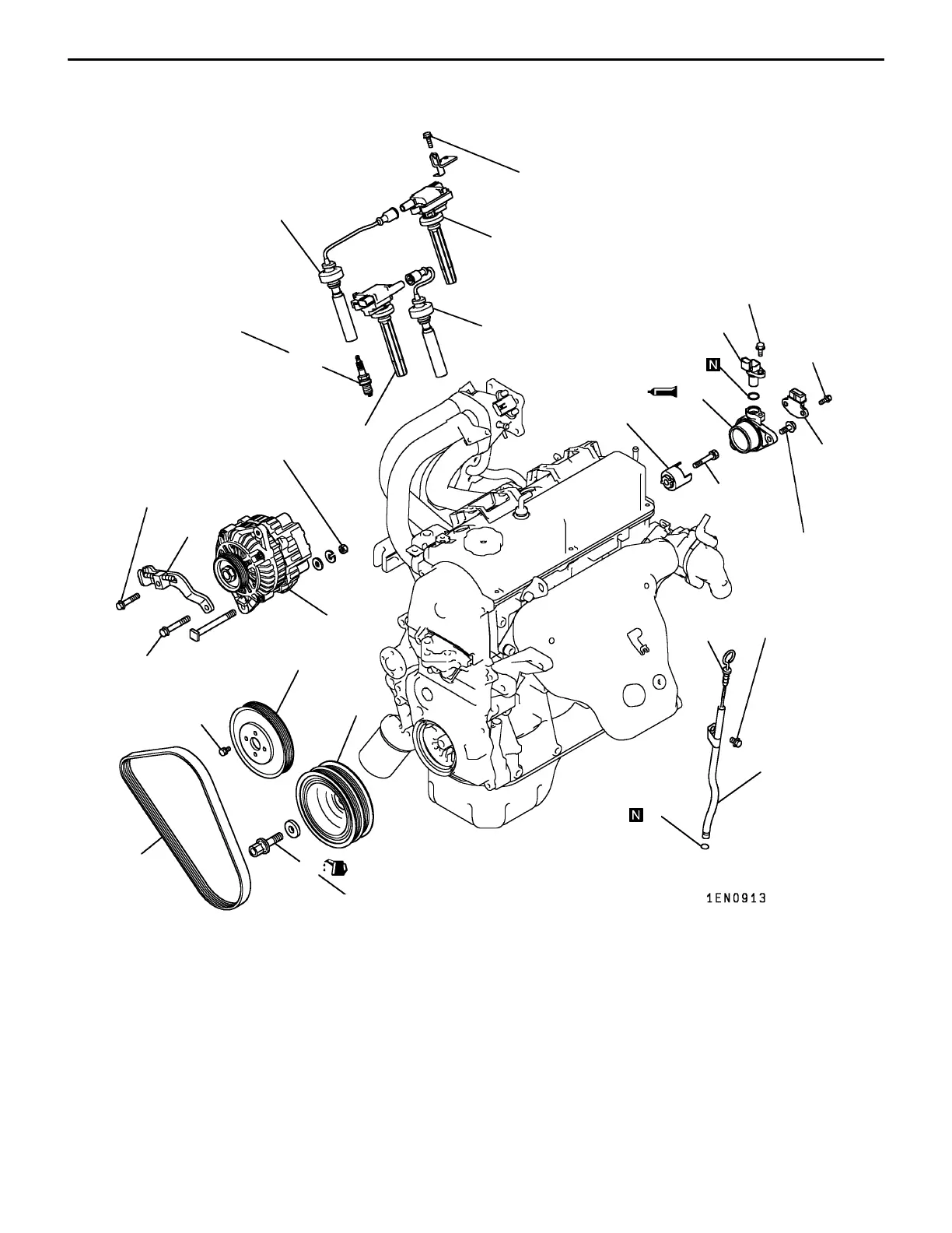
REMOVAL AND INSTALLATION <SOHC 16-VALVE – FRONT WHEEL DRIVE (WITH
CAM POSITION SENSOR)>
22 Nm
6
7
44 Nm
23 Nm
4
8
9
3
2
23 Nm
11
10 Nm
10
13
13 Nm
9 Nm
5
14
21 Nm
12
25 Nm
9 Nm
10
11
5 Nm
15
16
1
M12 125 Nm
M14 181 Nm
Removal steps
1. Oil level gauge
2. Oil level gauge guide
3. O-ring
4. Drive belt*
5. Water pump pulley
6. Alternator brace
7. Alternator
AA""BA 8. Crankshaft bolt
"BA 9. Crankshaft pulley
10. Spark plug cable
11. Ignition coil
12. Spark plug
13. Ignition failure sensor
(only vehicles for Europe)
14. Cam position sensor
"CA 15. Cam position sensor support
16. Cam position sensing cylinder
NOTE
*: For details of adjustment, refer to the relevant model’s
chassis workshop manual.
PWEE9520-G
E
Apr. 2003Mitsubishi Motors Corporation Revised
 Loading...


