FX Series Programmable Controlers Applied Instructions 5
5-77
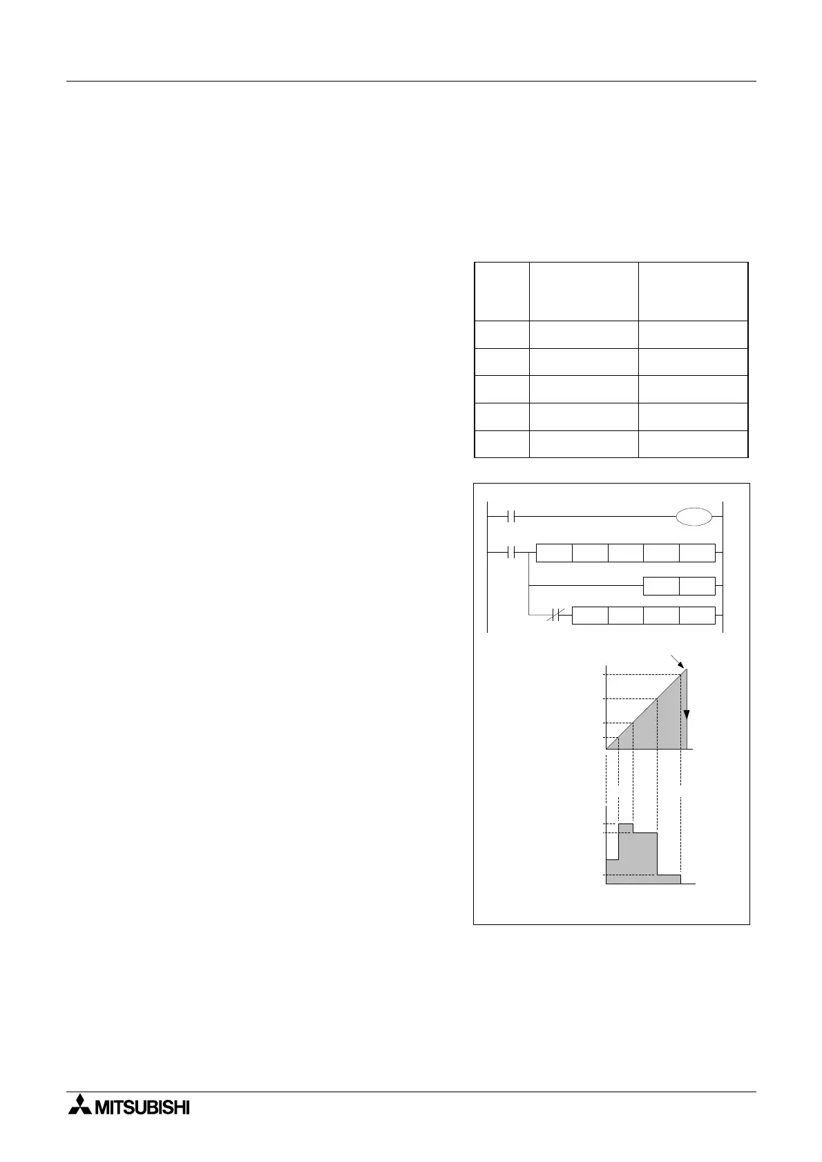
Operation 3 - Combined HSZ and PLSY Operation: (Applicable units: FX2N and FX2NC)
Operation 3 allows the HSZ and PLSY instructions to be used together as a control loop. This
operation is selected when the destination device (D) is assigned special M coil M8132. This
then allows devices (S
1,S2)tobeusedtodefineadatatableusing(S1) as the head address
and (S
2) as the number of records in the table - maximum number of records is 128. Each
record occupies 4 consecutive data registers (D through D
+3) proportioned in to two 32 bit data
areas.
The first pair of data registers (D,D
+1) contain
the comparison value for use with the high
speed counter. The second pair of data
registers (D
+2,D+3) contain a value (from 0 to
1000) which represents an output frequency in
Hz. This value is loaded in to special data
register D8132 when the comparison made by
the DHSZ instruction gives a ‘TRUE’ output.
Special data register D8132 can be used as the
source data for a PLSY (FNC57) output
enabling the output to be varied with relative
count data.
As with Operation 2 only one record in the data
tableisactiveatanyonetime.Thecurrent
‘Record number’ being processed is stored in
data register D8131. To observe the current
comparative value, data registers D8134 and
D8135 should be monitored as a double word
(32 bit) device.
Once the final entry in the data table has been
processed, the operation complete flag M8133
is set ON and the record counter (D8131) cycles
back to the first record.
It is recommended that if the high speed counter
and PLSY operations form a closed loop that
the last record entry in the data table is set to K0
for the comparison value and K0 for the PLSY
output frequency. This will bring the controlled
system to a stop and the ‘Record number’
counter will not be able to cycle back to the start
of the data table until the associated high speed
counter is reset by either pro-gram or hardware
methods. This situation can be easily monitored
by checking the paired data registers D8134
and D8135 for the ‘0’ value.
It is recommended that the operation of the
PLSY instruction is delayed for 1 scan to allow
the DHSZ data table to be constructed on initial
operation. A suggested program using a pulsed
flag is shown in the example on this page.
0
1
Record
number
[D8131]
Comparison value
(lower/upper
register)
[D, D
+1
]
Output Frequency
For PLSY
Instruction
[D
+2
,D
+3
]
2
3
4
[D180, D181]
K40
[D184, D185]
K100
[D188, D189]
K400
[D192, D193]
K800
[D196, D197]
K0
[D182, D183]
K100
[D186, D187]
K600
[D190, D191]
K550
[D194, D195]
K40
[D198, D199]
K0
40
100
400
800
D8131
C251 - count value
equals HSZ
comparison value
C251 reset
M8000
K9999
M8132C251DHSZ D180
K5
C251
X17
100
600
550
40
PLSY Output Frequency in Hz
0
1
324
D8132, output value
in Hz for PLSY
instruction
M10
PLS M10
PLSY
D8132
K0 Y7
1
32
1
32

 Loading...