FX Series Programmable Controller Diagnostic Devices 6
6-7
6.2 PLC Status (M8000 to M8009 and D8000 to D8009)
Diagnostic
Device
Operation
Diagnostic
Device
Operation
M8000 (
7)
RUN monitor
NO contact
D8000 (-)
Watchdog
timer
FX
1S,FX1N,FX2N,FX2NC:
200ms
See note 1
M8001 (
7)
RUN monitor
NC contact
D8001 (7)
PLC type and
version
FX1S:22
FX
1N:26 E.g. 26100 = FX1N, V1.00
FX2N:24
FX
2NC:24
M8002 (7)
Initial pulse
NO contact
D8002 (
7)
Memory
capacity
(see also D8102)
0002: 2K steps (FX1S only)
0004: 4K steps (FX
2N,FX2NC)
0008: 8K or 16k steps (FX
1N,
FX
2N,FX2NC)
M8003 (7)
Initial pulse
NC contact
D8003 (
7)
Memory type
00H = Option RAM,
01H = Option EPROM,
02H = Option EEPROM,
0AH = Option EEPROM
(protected)
10H = Built-in MPU memory
M8004 (7)
Error
occurrence
ON when one or more error
flags from the range M8060
to M8067 are ON
D8004 (7)
Error number
MPPPP
The contents of this register 2222
identifies which error flag is active, i.e.
if 2222 = 8060 identifies M8060
M8005 (7)
Battery voltage
Low
(Not FX1S,FX1N)
On when the battery
voltage is below the value
set in D8006
D8005 (
7)
Battery voltage
(Not FX1S,FX1N)
E.g. 36 = 3.6 volts
M8006 (
7)
Battery error
latch
(Not FX1S,FX1N)
Latches the battery Low
error
D8006 (
7)
Low battery
voltage
(Not FX1S,FX1N)
The level at which a low
battery voltage is detected
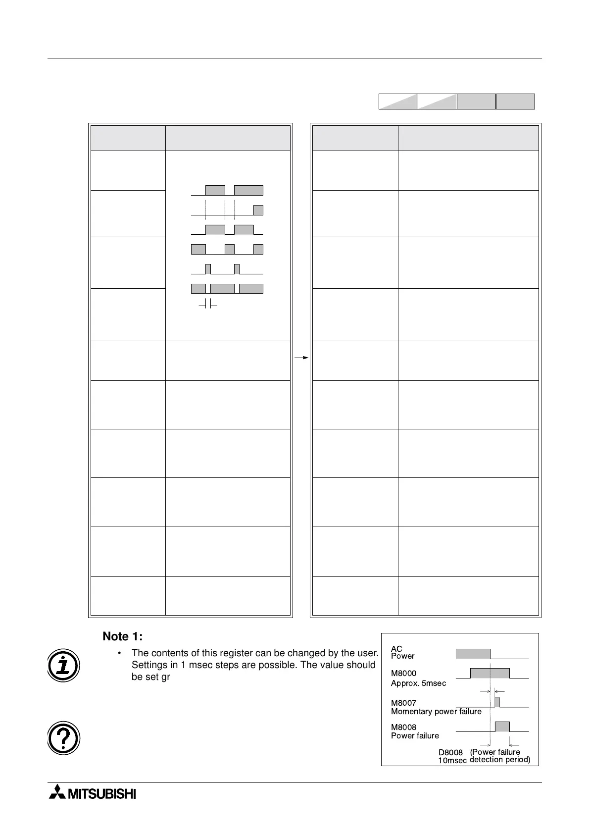
M8007 (
7)
Momentary
power failure
(Not FX1S,FX1N)
See note 2
D8007 (
7)
Power failure
count
(Not FX1S,FX1N)
The number of times a
momentary power failure has
occurred since power ON.
M8008 (
7)
Power failure
(Not FX1S,FX1N)
Power loss has occurred
See note 2
D8008
Power failure
detection.
(Not FX1S,FX1N)
Thetimeperiodbeforeshut
down when a power failure
occurs (default 10ms)
See note 2
M8009 (
7)
24V DC Down
(Not FX1S,FX1N)
Power failure of 24V DC
service supply
D8009 (
7)
24V DC failed
device
(Not FX1S,FX1N)
Lowest device affected by 24V
DC power failure
FX
1S
FX1N FX2N
FX2NC
RUN
Input
M8061 error occurence
M8000
M8001
M8002
M8003
Program scan time
AC
Power
M8000
M8007
Approx. 5msec
Momentary power failure
M8008
Power failure
D8008
10msec
(Power failure
detection period)
Note 1:
• The contents of this register can be changed by the user.
Settings in 1 msec steps are possible. The value should
be set greater than the maximum scan time (D8012) to
ensure constant scan operation.
Note 2:
• When the power supply used is 200V AC, the power
down detection period is determined by the value of
D8008. This can be altered by the user within the
allowable range of 10 to 100msec.
For symbol key see page 6-1.

 Loading...