EasyManua.ls Logo

Mitsubishi FX1S Series User Manual

Mitsubishi FX1S Series
466 pages
To Next Page IconTo Next Page
To Previous Page IconTo Previous Page
Page #440 background imageLoading...
Page #440 background image
FX Series Programmable Controllers Points Of Technique 10
10-22
FX2N (V2.00 or above) Communications
In the FX2N V2.00 or above and FX2NC, full duplex communication is performed.
1) No Hardware Handshaking D8120 (B12, b11, b10) = (0,0,0)
2) Terminal Mode
The control line and transmission sequence are identical to those in the FX, on page
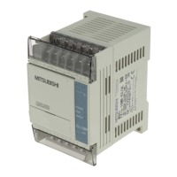
3) Normal Mode 1 D8120 (b12, b11, b10) = (0, 1, 1)
FX
1S
FX
1N
FX
2N
FX2NC
Resetitusingaprogram.
When it is not turned off, the
next data cannot be received.
Data 1
RS
instruction
Send data
SD (TXD)
OFF ON
Data 5
OFF
ON
Send request
M8122
Receive
completion
M8123
Data 3
Data 2
Data 4
OFF
ON
ON
The receive wait
status is started
Receive data
RD (RXD)
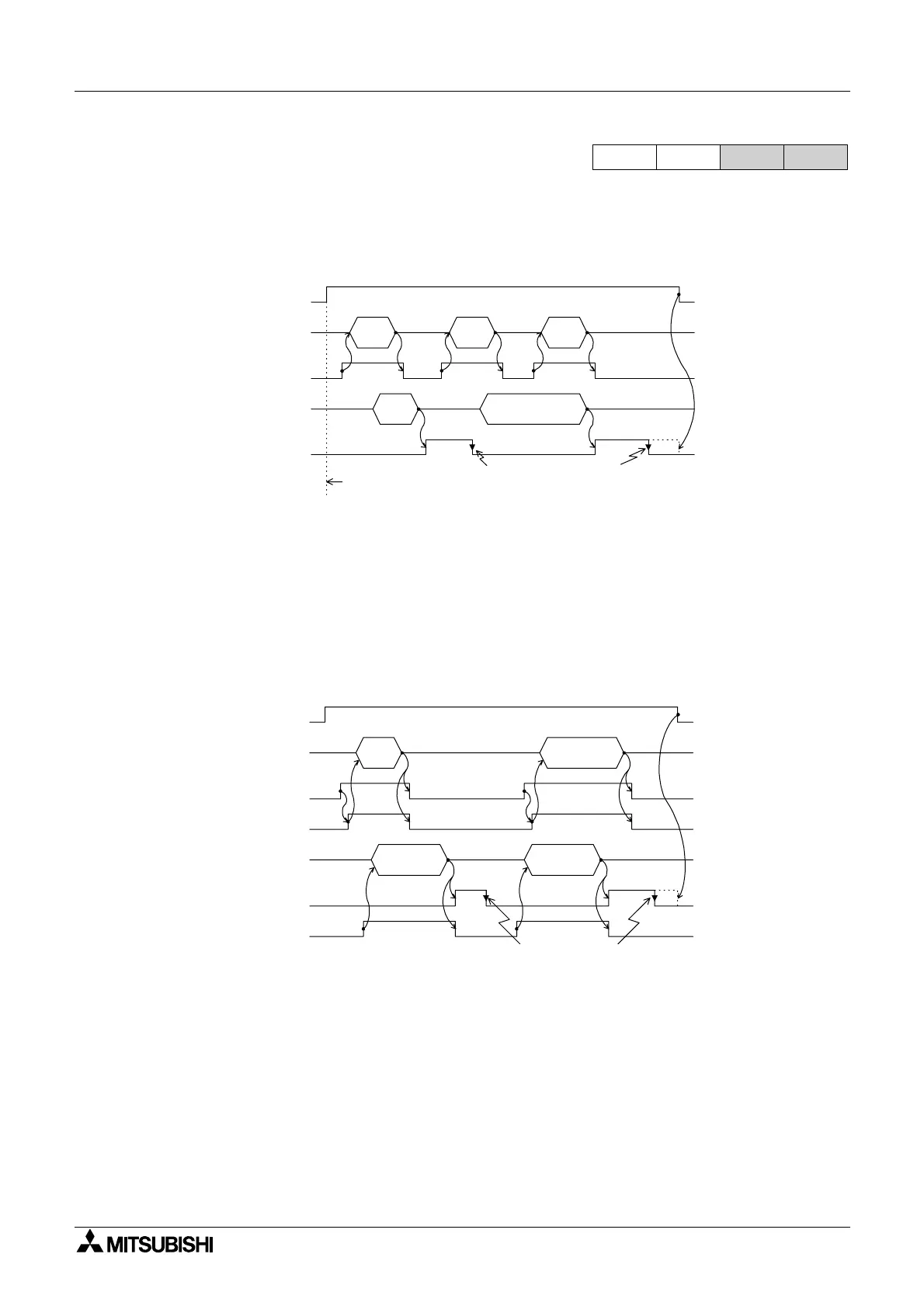
Reset using a program.
When it is not turned off, the
next data cannot be received.
Data 1
OFF
OFF ON
ON
Data 4
OFF ON
RS
instruction
Send data
SD (TXD)
ER(DTR)
ON
Receive
completion
M8123
OFF ON
Data 2 Data 3
Receive data
RD (RXD)
OFF ON
Send request
M8122
DR(DSR)

Table of Contents

Other manuals for Mitsubishi FX1S Series

Question and Answer IconNeed help?

Do you have a question about the Mitsubishi FX1S Series and is the answer not in the manual?

Mitsubishi FX1S Series Specifications

General IconGeneral
ModelFX1S Series
I/O Points10 to 30 points
Program Memory2000 steps
Power SupplyAC
CommunicationRS-422
ExpansionNo expansion
Programming LanguageLadder Logic
Input Voltage100-240V AC
Built-in High-Speed CounterUp to 60 kHz (single-phase)
WeightApprox. 0.3 kg
Dimensions90 x 60 x 75 mm

Summary

Basic Program Instructions

How to Read Ladder Logic

Explains the principles of ladder logic, contacts, coils, and how to interpret their operation.

STL Programming

How STL Operates

Explains STL's operation as a flow chart system, organizing programs into states or steps for better manageability.

How To Start And End An STL Program

Covers the essential methods for starting and terminating STL programs, including embedded programs and activating new states.

Devices in Detail

Inputs

Details the 'X' device mnemonic for physical inputs, its available forms, numbering, and example usage.

Outputs

Explains the 'Y' device mnemonic for physical outputs, available forms, numbering, and provides a table of available devices.

Auxiliary Relays

Introduces the 'M' device mnemonic for internal status flags, listing different types and their availability.

State Relays

Covers the 'S' device mnemonic for internal status flags, detailing general, battery-backed, STL step relays, and annunciator flags.

Timers

Details the 'T' device mnemonic for timed durations, including available resolutions, retentive timers, and timers used in subroutines.

Data Registers

Describes the 'D' device mnemonic for storing numeric data or patterns, including general, latched, special, file, and externally adjusted registers.

Applied Instructions

Move And Compare - Functions 10 to 19

Explains instructions for moving and comparing data, including CMP, ZCP, MOV, SMOV, CML, BMOV, FMOV, XCH, BCD, and BIN.

Arithmetic And Logical Operations - Functions 20 to 29

Covers instructions for arithmetic operations like ADD, SUB, MUL, DIV, INC, DEC, and logical operations like WAND, WOR, WXOR, NEG.

High Speed Processing - Functions 50 to 59

Covers instructions for high-speed operations like REF, REFF, MTR, HSCS, HSCR, HSZ, SPD, PLSY, PWM, and PLSR.

External FX I/O Devices - Functions 70 to 79

Explains instructions for interfacing with external FX I/O devices, such as TKY, HKY, DSW, SEGD, SEGL, ARWS, ASC, PR, FROM, and TO.

External FX Serial Devices - Functions 80 to 89

Covers instructions for serial communication with external FX devices, including RS, PRUN, ASCI, HEX, CCD, VRRD, VRSD, PID.

Floating Point 1 & 2 - Functions 110 to 129

Explains instructions for floating-point arithmetic and conversions, including ECMP, EZCP, EBCD, EBIN, EADD, ESUB, EMUL, EDIV, ESQR, and INT.

Positioning Control - FNC 150 to FNC 159

Explains instructions for controlling positioning operations, including ABS, ZRN, PLSV, DRVI, and DRVA.

Diagnostic Devices

PLC Status (M8000 to M8009 and D8000 to D8009)

Details special PLC status bits and registers, including watchdog timer, PLC type, and power failure flags.

Operation Flags (M8020 to M8029 and D8020 to D8029)

Describes operation flags like Zero, Borrow, Carry, BMOV reverse mode, HSC instructions, RAMP hold mode, and instruction execution completion.

Error Detection Devices (M8060 to M8069 and D8060 to D6069)

Lists devices used for detecting errors such as I/O configuration, PLC hardware, communication, parameter, syntax, and program construction errors.

Error Code Tables

Lists and explains various error codes related to PLC hardware, communication, parameter, syntax, and operation errors.

Instruction Execution Times

Basic Instructions

Provides execution times in microseconds for basic instructions like LD, LDI, AND, OR, MPS, INV, MC, MCR, NOP, END, STL, and RET across different PLC models.

Applied Instructions

Lists execution times in microseconds for applied instructions like CJ, CALL, MOV, SMOV, BMOV, etc., for various PLC models and configurations.

PLC Device Tables

Performance Specification Of the FX1S

Details the performance specifications for the FX1S PLC, including I/O configuration, timers, counters, and data registers.

Performance Specification Of The FX1N

Outlines the performance specifications for the FX1N PLC, covering operation modes, instructions, memory, and device allocations.

Performance Specification Of The FX2N and FX2NC PLC’s

Provides performance specifications for FX2N and FX2NC PLCs, detailing timers, counters, data registers, pointers, and constants.

Assigning System Devices

Addressing Extension Modules

Explains how to address additional discrete I/O and special function modules, including cautions for specific FX units.

Real Time Clock Function

Details the RTC function, its battery backup, accuracy, and calendar capabilities, including setting the real-time clock.

Points of Technique

Using The Forced RUN/STOP Flags

Explains how to implement external RUN/STOP control using push buttons and the associated PLC wiring and program.

Using The PWM Instruction For Motor Control

Explains how to use the PWM instruction for motor control, including circuit configuration, parameter setting, and characteristics.

PID Programming Techniques

Covers PID control techniques, including keeping MV within range, manual/automatic switching, alarm signals, and general programming tips.

Related product manuals