FX Series Positioning Controllers Program format 5
5-42
5.7.3 Bit devices
The devices such as X, Y and M which handle ON/OFF information are called bit devices. Other
devices such as D, V and Z which handle numeric data are called word devices. Bit devices,
however, can be grouped to handle numeric data. The combination of bit devices is expressed by
a digit "n" following "K" (Kn) and the head device No.
The bit devices can be grouped in unit of 4 bits. The "n" in KnM0 defines the number of groups of
4 bits to be combined for data operation.
K1 to K4 are allowed for 16-bit data operation, and K1 to K8 are allowed for 32-bit data operation.
For example, K2M0 indicates 2 groups of 4 bits using the bit devices M0 to M7.
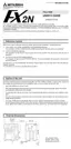
When 16-bit data is transmitted to K1M0 to K3M0, the overflowing bit data is not transmitted.
This is also true for 32-bit data.
When a 16-bit (32-bit) data operation is executed and the digit specification for a bit device is
K1 to K3 (K1 to K7), "0" is placed in the higher digit bit positions.
For example, if K4Y00 is used for a 32 bit data operation, the upper 16 bits are regarded as "0".
If 32-bit data with the sign is required, K8Y00 must be specified.
Any bit device No. can be used. However, it is recommended to use "0" in the lowest digit place
of the X and Y No. (X00, X10, X20 . . ., Y00, Y10, Y20, etc.).
For M, it is ideal to use multiples of 8. However, because the use of such No. may lead to con-
fusion in assigning device No., it is recommended to use multiples of 10 such as M0, M10,
M20, etc. in the same way as X and Y.
Specification of series of words
A series of data registers beginning with D1 means D1, D2, D3, D4,
xxx
.
When grouped bit devices are used for a series of words, they will be specified in the following way.
K1X00, K1X04, K1X14,
xxx
; K2Y10, K2Y20, K2Y30,
xxx
;
K3M0, K3M12, K3M24, K3M36,
xxx
.
That is, all bit devices will be used so that no device is skipped.
100
0
0000
0
00 0101
100
101
0
101
0
01
0
1
10
0
101
01
M15
M14 M13 M12 M11 M10 M 9 M 8 M 7 M 6
M 5
M 4M 3M 2M 1M 0
1
1
D 0
D 1
K2M 2
Sign bit
(0:Positive, 1:Negative)
Transfer
Transfer
Lower bits
Lower bits
The unspecified devices remain unchanged.
Sign bit
(0:Positive, 1:Negative)
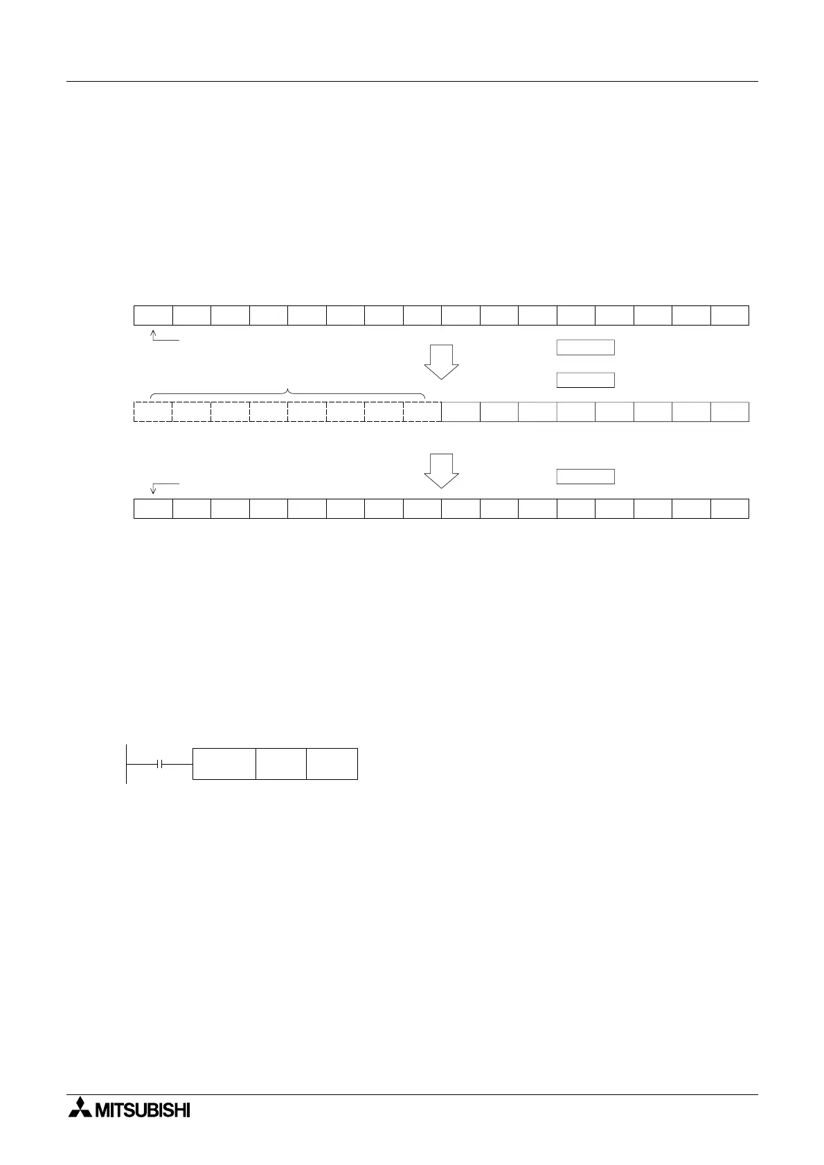
BIN K2X04 D 0
M 0
2-digit BCD data from X04 to X13 is
converted into binary data and
transmitted to D0.

 Loading...