FX Series Positioning Controllers Introduction 1
1-4
1.4 Product composition
1.4.1 Part names
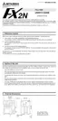
The name and description of each part of the FX
2N
-10GM are explained below.
➀
Operation indicator LED
➅
Hook for DIN rail installation
➁
MANU/AUTO switch
➆
Connector for motor amplifier: CON2
➂
Connector for programming tool
➇
Connector for I/O: CON1
➃
I/O display
➈
Connector for power supply
➄
Connector for PLC extension block
➉
Connector for PLC
The name and description of each part of the FX
2N
-20GM are explained below.
a)Battery (Refer to Section 11.) k) Connector for PLC extension block
b)Operation indicator LED l) Hook for DIN rail installation
c) MANU/AUTO switch m)Connector for y axis motor amplifier: CON4
d)Connector for programming tool n)Connector for x axis motor amplifier: CON3
e)General-purpose I/O display o)Connector for input equipment: CON2
f) Display for equipment inputs p)Connector for power supply
g)x axis status display q)Connector for general-purpose I/O: CON1
h)Lock to fix extension block of FX
2N
-20GM r) Connector for memory board
i) y axis status display s) Connector for PLC
j) Connector for FX
2N
-20GM extension block
ZRN
FWD
Y4
Y5
RP
STOP
FP
X2
X3
Y0
Y1
Y2
START
Y3
CLR
AUTO
MANU
POWER
READY
ERROR
CPU-E
X0
RVS
DOG
LSF
LSR
X1
PGO
SVRDY
SVEND
FX -10GM
2N
➀➃
➈
➇
➆
➅
➂➁
➄
Accessories
Power supply cable
FX
2NC
-100MPCB 1
Connection cable
FX
2N
-GM-5EC 1
➉
➅
FX -20GM
FWD
ZRN
STOP
START X
RVS
DOG
READY-y
ERROR-x
READY-x
BATT
Y4
7
5
1
3
2
1
Y0
6
5
X4
3
2
X0
7
6
START Y
STOP
ZRN
FWD
RVS
DOG
LSF
LSR
SVEND
CLR
RP
FP
PG0
CPU-E
ERROR-y
POWER
MANU
AUTO
Y4
X7
Y5
X1
Y3
Y2
Y1
Y0
X6
X5
X4
X3
X2
X0
Y7
Y6
SVRDY Y
SVEND
PG0
FP
RP
CLR
LSF
LSR
SVRDY-X
2N
a)
d) e)c)b)
l)
f)
j)
i)
h)g)
k)
r) n)o) m)p)
s)
h)q)
r)
Accessories
Power supply cable
FX
2NC
-100MPCB 1
FX
2NC
-100BPCB 1
Connection cable
FX
2N
-5EC 1

 Loading...