FX Series Positioning Controllers Program format 5
5-60
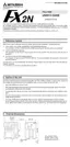
5.10.20 FNC72 (EXT): Time-sharing reading of digital switches
Reading of a positive value
1) Head input No. (Occupies 4 input points.)
The connections in this example are as follows.
X00: Terminal 1 of DSW
X01: Terminal 2 of DSW
X02: Terminal 4 of DSW
X03: Terminal 8 of DSW
2) Head output No. for time-sharing operation (Occupies 1 to
8 output points.)
The connections in this example are as follows.
Y00: Terminal C of DSW (100 digit)
Y01: Terminal C of DSW (101 digit)
Y02: Terminal C of DSW (102 digit)
Y03: Terminal C of DSW (103 digit)
3) Data storage destination
When a 16-bit instruction is executed, a digital switch BCD
value of up to 4 digits is converted into binary data and
saved in D0.
When a 32-bit instruction is executed, a digital switch BCD value of up to 8 digits is con-
verted into binary data and saved in (D1, D0).
↑
↑
Upper 4 digits Lower 4 digits
4) Number of digits
K1 to K4 are used with 16-bit instructions, and K5 to K8 are used with 32-bit instructions.
(Refer to the right page.)
The same number of digit-switching output points as the specified number of digits is
required.
In the FX
2N
-10GM, K1 to K6 (6 digits) are available.
FNC 72
EXT
Applicable models
Series name
Remarks
X Y M
K,H KnX KnY KnM D V,Z
Applicable
devices
and basic
format
Word
devices
Bit
devices
FNC 72
EXT
FX
2N
-10GM
FX
2N
-20GM
EXTERNAL
EXT
[D] EXT
Time-sharing reading of digital switches
Head input
Head ouput
Data
storage
destination
The data is read from the digital
switches using the time-sharing
method.
Drive
input
S· D1· D2·
n
n
Number of
digits
S·
S2·
D1·
16-bit operation
9 steps
16-bit operation
14 steps
•
FNC 72
EXT
X00 Y00 D 0 K 4
M 0
S· D1· D2·
n
This instruction performs time-sharing
reading of the data from the digital switches.
(1) (2) (3) (4)
1423
X03 X02 X01 X00
Y03 Y02 Y01 Y00
8 4 2 1
Extension block
Internal circuit of the digital switch.
8 4 2 1
C C
C C
C
8 4 2 1
8 4 2 1
8 4 2 1 8 4 2 1 8 4 2 1

 Loading...