FX Series Positioning Controllers Introduction 1
1-8
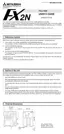
1.4.5 System configuration and I/O assignment
FX
2N
-10GM
The FX
2N
-10GM is equipped with a power supply, a CPU, operation system inputs, mechanical
system inputs and an I/O drive unit. It can also operate inclependantly.
The FX
2N
-10GM is equipped with four input points (X0 to X3) and six output points (Y0 to Y5)
for general purpose, and can be connected to external I/O equipment. If I/O points are not suf-
ficient, use the FX
2N
-10GM together with an FX
2N
/
2NC
Series PLC.
At this time, the FX
2N
-10GM is treated as a special unit of the PLC. Up to eight special units
(including FX
2N
-10GM, analog I/O and high-speed counter) can be connected to an FX
2N
Series PLC. Up to four special units (including FX
2N
-10GM, analog I/O and high-speed
counter) can be connected to an FX
2NC
Series PLC.
I/O assignment shown inside ( ) indicates I/O points in the FX
2N
-10GM.
I/O assignment
The FX
2N
-10GM units are treated as special units of the PLC. From the one nearest to the
PLC, the special unit Nos. 0 to 7 are automatically assigned to the connected special units.
(This special unit No. is used the by FROM/TO instructions.)
Separate from I/O points in the PLC, and general-purpose I/O points in the FX
2N
-10GM are
controlled as I/O points in the FX
2N
-10GM. (One PLC occupies eight I/O points.)
For the details of assignment of I/O points in the PLC, refer to the FX
2N
/
2NC
Series Hardware
manuals.
1
IN 0
7
2
3
4
5
6
POWER
1
IN 0
7
2
3
4
5
6
ZRN
FWD
Y4
Y5
RP
STOP
FP
X2
X3
Y0
Y1
Y2
START
Y3
CLR
AUTO
MANU
POWER
READY
ERROR
CPU-E
X0
RVS
DOG
LSF
LSR
X1
PGO
SVRDY
SVEND
FX -10GM
2N
72456130
1611 1514 1710 12 13
14 171510 12 13
72456130
1611
OUT
IN
LX13X15
X10 X14 X16
24+N
COM X4
X7
Y4
Y5
Y6
COM3
Y10
Y11
Y12
Y13Y1
Y2
Y3
Y14
Y15
X3
X2
X1
POWER
BATT.V
RUN
CPU.E
PROG.E
1
OUT 0
7
2
3
4
5
6
POWER
1
OUT 0
7
2
3
4
5
6
ZRN
FWD
Y4
Y5
RP
STOP
FP
X2
X3
Y0
Y1
Y2
START
Y3
CLR
AUTO
MANU
POWER
READY
ERROR
CPU-E
X0
RVS
DOG
LSF
LSR
X1
PGO
SVRDY
SVEND
FX -10GM
2N
X000 to X017
X020 to X027
(X00 to X03)
Special unit No. 0
(X00 to X03)
Special unit No. 1
Y000 to Y017
(Y00 to Y05)
(Y00 to Y05)
Y020 to Y027
Extension block for
PLC main unit

 Loading...