FX Series Positioning Controllers Specifications 2
2-6
2.5 Output Specification
Pulse output waveforms
The following types of pulse waveforms are output to a drive unit.
You do not have to set the pulse output waveform using parameters. The pulse output wave-
form automatically changes in accordance with the practical frequency.
1) In the case of interpolation drive instructions (FX
2N
-20GM)
When a simultaneous 2-axis drive instruction (cod 01/02/03/31) is given, the following wave-
form is acquired at the operation frequency of 1 Hz to 100 kHz.
2) In the case of other drive instructions
• When the operation frequency in the FX
2N
-20GM is 200 to 101 kHz, the ON period is fixed
to 2.5
µ
s. Accordingly, the ON period becomes equivalent to the OFF period at 200 kHz.
• When the operation frequency in the FX
2N
-20GM is 100 kHz to 1 Hz, the ON/OFF ratio is
50%/50%.
• When the operation frequency in the FX
2N
-10GM is 200 kHz to 1 Hz, the ON/OFF ratio is
50%/50%.
Table 2.6: Output Specification
Item General-purpose output Output to drive unit
Signal name Y00 to Y07 FP, RP, CLR
Output circuit
configuration
Circuit isolation By photocoupler
Operation indication LED is lit while output is ON
External power supply 5 to 24V DC ± 10%
Load current 50mA or less 20mA or less
Open circuit leak current 0.1mA/24V DC or less
Output ON voltage 0.5V max (CLR is 1.5V max.)
Response time
0.2ms max. for both OFF
→
→→
→
ON and
ON
→
→ →
→
OFF.
Pulse output FP RP is 200kHz max.
Pulse output width of the CLR signal:
Approx. 20msec.
Turning ON rate of I/O
simultaneously
50% or less (FX
2N
-20GM)
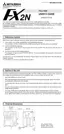
COM
Output
5V to 24V
Load
5
µ
s(constant)
ON
OFF

 Loading...