FX Series Positioning Controllers Wiring 3
3-9
• Output terminals:
The output terminals of the positioning unit are located in a 16-point connector in which both
inputs and outputs are located.
The power supply for driving the loads must be 5 to 30V DC smoothed power supply.
• Circuit isolation:
The internal circuits of the positioning unit are isolated optically from the output transistors
by a photocoupler. In addition, each common block is isolated from the others.
• Operation indication:
When a photocoupler is driven, the LED is lit and the output transistor is turned ON.
• Output current:
Refer to Section 2.5.
The ON voltage of an output transistor is approximately 1.5 V.
When driving semiconductors, etc., make sure that the input voltage of the device does not
exceed this value.
• Response time:
For the response time between activation or deactivation of a photocoupler and turning ON
or OFF of an output transistor, refer to Section 2.5.
• Leak current in open circuit:
The leak current is 0.1 mA or less.
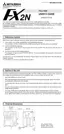
LED
+
12V
Photocoupler
Positioning unit
50V
Zener
5 to 24V DC
COM1
Y000

 Loading...