FX Series Positioning Controllers Wiring 3
3-23
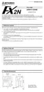
When the FX
2N
-20GM is connected to the MR-H servo motor.
19
11
12
17
18
9
1
2
COM3/7
Y01
Y00
COM1
X07
X06
X01
X00
COM1
18
11
12
13
14
15
16
17
LSR
LSF
DOG
RVS
FWD
ZRN
STOP
START
COM1
Y02 3
Y03 4
Y06 7
Max
50mA
CON1
Y07 8
1
COM2/6
2
COM2/6
12
SVEND
11
COM4/ 8
14
PGO
13
VIN
7,8,
17,18
FPO 5
FP 6
COM5/9
9,19
RP 16
RPO 15
CLR 3
4
SVRDY
19 9
1
2
3
4
5
6
7
8
CON1
X02 13
X03 14
X04 15
X05 16
5Y04
6Y05
2
12
11
14
13
7,8,
17,18
5
9,19
6
16
15
3
4
1
50SD
VDD
PF
OP
VDD
PPO
SG
NPO
CN1
CR
RD
P15R
CN1
CN1
SG
MO1
37
19
47
18
22
33
1
24
22
49
17
1
40
SG
39
LSN
38
LSP
15
RES
12
SON
46
EMG
20
VIN
21
VDD
45 DI4
44 DI3
12 SON
Max 200mA
CN1
CN1
48 ALM
ZSP
TLC
VDD21
23
25
CN1
SG16
TLC25
23 ZSP
4
MOG
2
MO2 A
PG
A
NCP
R
S
T
S1
E
W
V
U
E
W
V
U
R1
CN2
CN3
CN4
AC200
- 230V
MFB MC
M
MR-PRU01
FX
2N
-20GM
DC24V
CON4
y axis
CON3
x axis
ST1/3 10
20
10
20
5 to 24V
24-
24+
x axis
y axis
3.3k
W
3.3k
W
3.3k
W
2k
W
150k
W
3.3k
W
3.3k
W
Automatic
Start
Stop
Zero return
Manual forward rotation
Manual reverse rotation
Near-point signal
Forward rotation limit
Reverse rotation limit
5 to 24V
General purpose inputs
General purpose outputs
Cable length: 2m max.
Y axis
X axis
The EN and x/y
entries ars examples.
31
ZRN
X372
FWD
X373
X374
A
72 - x
B
72 - x
71 - y
RVS
Manual
Table: Assignment of
X00 to X07.
EN
Automatic
X375
X376
X377
72 - y
72 - y
71 - x
x / y
x - A
x - B
y - A
y - B
x - EN
y - EN
Manual pulse
generator
Interrupt
input
Optional
cable
Optional
cable
The optional cable
(E-GMH-200CAB) is provided
for the positioning unit.
MR-H A servo amplifier.
Connect to the positioning unit when detecting absolute position.
*1.
Zero speed
Fault
Torque limit
*1
*1
External
emergency stop
Servo ON
Forward
rotation limit
Reverse
rotation limit
Reset
*1
Regenerative option
HA- H
Servo motor
Connect so that MC is turned
OFF by alarm or emergency stop.
Monitor 1
Monitor 2
Parameter
unit
Absolute
position
detection
Do the ground
wiring with
of the servo
amplifier.
ST2/4

 Loading...