145
FX3UC Series Programmable Controllers
User’s Manual - Hardware Edition
5 Input Specifications and External wiring
5.2 24V DC Input Type
1
Outline
2
External
Dimensions
3
Generic
Specifications
4
Power Supply
Specifications
5
Input
Specifications
6
Output
Specifications
7
Examples of
Wiring for
Various Uses
8
Terminal Block
9
CC-Link/LT
Master FX
3UC
(LT only)
10
Display module
FX
3UC
(LT only)
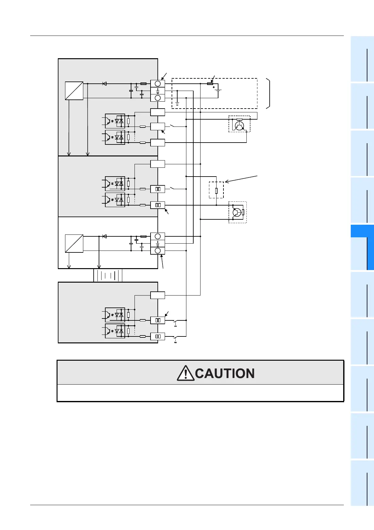
2. Examples of sink input wiring (Common to both sink and source input types)
WIRING PRECAUTIONS
• Before cleaning or retightening terminals cut off all phases of the power supply externally.
Failure to do so may cause electric shock.
FX
3UC
-32MT/DSS
FX
2NC
extension block
(Common to both sink
and source input types)
FX
3UC
-1PS-5V
+
-
COM0
X000
X001
Input
impedance
5V 24V
COM
X
0
X
1
+
-
24V DC
Three-
wire
sensor
Input
terminal
Two-wire
proximity
sensor
FX
2N
extension block
(Common to both sink
and source input types)
S/S
*
DC/DC
converter
DC
DC
Input
terminal
* Class D grounding
The grounding resistance should be
100
Ω
or less.
Power
connector
Power
connector
Input
terminal
Fuse
5V 24V
DC/DC
converter
DC
DC
X
0
X
1
Photocoupler
Photocoupler
Photocoupler
For an input device having a
parallel resistance or a
two-wire proximity switch, a
bleeder resistance may be
required.
(Refer to Subsection 5.2.4.)
Handle the power supply
circuit correctly in
accordance with Chapter
4 "Power supply
specifications and
external wiring."
 Loading...


