173
FX3UC Series Programmable Controllers
User’s Manual - Hardware Edition
6 Output Specification and External Wiring
6.2 Transistor Output
1
Outline
2
External
Dimensions
3
Generic
Specifications
4
Power Supply
Specifications
5
Input
Specifications
6
Output
Specifications
7
Examples of
Wiring for
Various Uses
8
Terminal Block
9
CC-Link/LT
Master FX
3UC
(LT only)
10
Display module
FX
3UC
(LT only)
Source output
Two +V terminals (connected to each other inside the
PLC) are provided for sink outputs in the FX
3UC main unit,
transistor output type extension blocks (source type) for the
FX
2NC.
For external wiring, connect two +V terminals outside the
PLC so that the load applied on each +V terminal
becomes smaller.
2. External power supply
For driving the load, use a smoothing power supply of 5 to 30V DC that can output current two or more times
the rated current of the fuse connected to the load circuit.
3. Insulation of circuit
The internal circuit of the PLC and the output transistor are insulated with a photocoupler.
The common blocks are separated from one another.
4. Display of operation
Operation indicator LEDs are built into the main unit and output extension blocks, and turn ON when
photocouplers are actuated. The FX
3UC-32MT-LT does not have operation indicator LEDs, but the operation
can be monitored with the display module.
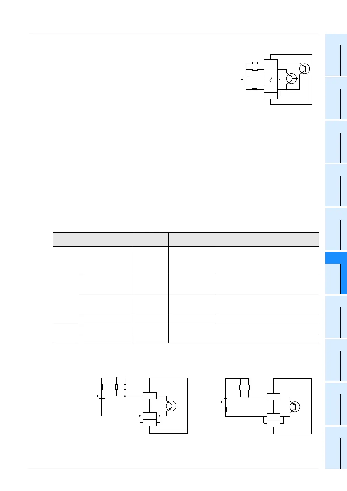
5. Response time
The time from when the PLC drives (or shuts down) the photocoupler until the transistor is turned on (or off) is
shown in the following table.
*1. The transistor OFF time is longer under lighter loads. For example, under a load of 24V DC 40mA, the
response time is approx. 0.3ms. When response performance is required under light loads, provide a
dummy resistor as shown below to increase the load current.
Classification
Response
time
Load current
Main units
Y000 to Y002 5 µs or less
5 to 24V DC 10mA
or more
When using an instruction related to pulse
train output or positioning, make sure to set
the load current to 10 to 100mA (5 to 24V
DC).
Y003
(FX
3UC-MT/
D, DSS)
0.2 ms or less
24V DC 100mA
*1
Y003
(FX
3UC-32MT-LT)
5 µs or less
5 to 24V DC 10mA
or more
When using an instruction related to
positioning, make sure to set the load
current to 10 to 100mA (5 to 24V DC).
Y004 to Y017 0.2 ms or less
24V DC 100mA
*1
Extension
blocks
For FX
2NC Series
0.2 ms or less
24V DC 100mA
*1
For FX0N/FX2N Series
24V DC 200mA
*1
• Sink output type • Source output type
PLC
Y000
Load
+V0
+V0
Y001
Source output type
5 to 30V
DC
Fuse
PLC
Y010
COM1
Dummy
resistance
Load
Fuse
COM1
PLC
Y010
+V0
Dummy
resistance
Load
Fuse
+V0
 Loading...


