236
FX3UC Series Programmable Controllers
User’s Manual - Hardware Edition
8 Terminal Block Specifications and External Wiring
8.10 FX-16EYT(-H)-TB
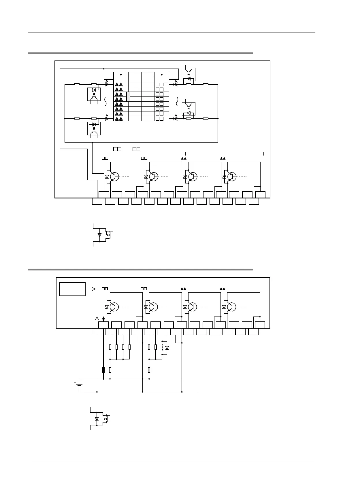
8.10.2 Internal circuit
8.10.3 Example of output external wiring
1 3
4
5
60 2
7 1 3
0 2 4
5
6
724+
24-
COM1
COM1
COM2
COM2
COM3
COM3
COM4
COM4
(20)
COM1
6
7
5
4
3
2
1
0
COM1
6
7
5
4
3
2
1
0
(10)
(19) (9)
(18) (8)
(17) (7)
(6)
(5)
(4)
(3)
(2)
(1)
(16)
(15)
(14)
(13)
(12)
(11)
0123 4567 0123 4567
Photo-
coupler
Photo-
coupler
3.3k
Ω
3.3k
Ω
Photo-
coupler
Photo-
coupler
*2. For the FX-16EYT-H-TB, the output transistor elements are as shown in the figure below.
*2 *2 *2 *2
0 to 7 Lower numbers
0 to
7 Higher numbers
3.3k
Ω
3.3k
Ω
*1
*1
*1."COM2" or "COM3" in accordance with connected connector
1 3
4
5
60 2
7 1 3
0 2 4
5
6
724+
24-
COM1
COM1
COM2
COM2
COM3
COM3
COM4
COM4
0123 4567 0123 4567
PLC output
No.
Photo-coupler
power supply
24V
DC
Fuse
*3 *3 *3 *3
*3 For the FX-16EYT-H-TB, the output transistor elements are as shown in the figure below.
Fuse
 Loading...


