85
FX3UC Series Programmable Controllers
User’s Manual - Hardware Edition
2 External Dimensions and Terminal Arrangement
2.1 External Dimensions (MASS/Installation/Accessories)
1
Outline
2
External
Dimensions
3
Generic
Specifications
4
Power Supply
Specifications
5
Input
Specifications
6
Output
Specifications
7
Examples of
Wiring for
Various Uses
8
Terminal Block
9
CC-Link/LT
Master FX
3UC
(LT only)
10
Display module
FX
3UC
(LT only)
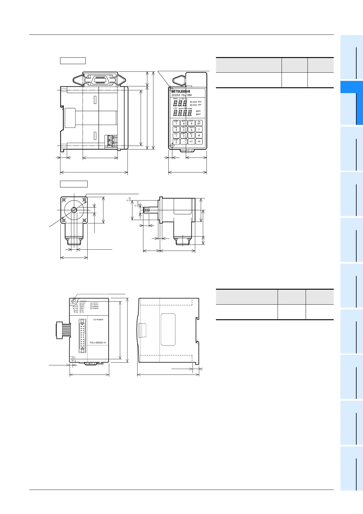
FX2N-1RM(-E)-SET
• Installation: DIN rail of 35 mm (1.38") in
width or screws
• Accessories: Label for indication of
special unit/block number,
FX
2N-RS-5CAB signal
cable (5m(16’4")),
F
2-720RSV resolver,
extension cable
(55mm(2.06")), Manual
supplied with product
• Terminal block: M3 screws
FX
3U-20SSC-H
• Installation: DIN rail of 35 mm (1.38") in
width or screws
• Accessories: Label for indication of
special unit/block number,
FX
2NC-100MPCB Power
supply cable (1m(3’3")),
Manual supplied with
product
• Terminal block: Connector
• The extension cable is already connected to
the extension block
Model name W(mm)
MASS
(Weight)
FX
2N-1RM(-E)-SET
55
(2.17")
0.5
(1.10lbs)
Model name W(mm)
MASS
(Weight)
FX
3U-20SSC-H
55
(2.17")
0.3
(0.66lbs)
55(2.17")
97(3.82")
80(3.15")
(mounting hole pitch)
90(3.55")
21
(0.83")
111(4.38")
Unit:mm (inches)
4
(0.16")
30
(1.19")
9
(0.36")
50
(1.97")
2-φ4.5 mounting holes
FX2N-1RM
F2-720RSV
10
(0.4")
3
4514
Unit:mm (inches)
MASS(Weight):0.41kg(0.88lbs)
9.5(0.38")
28
(1.11")
60
(2.37")
45(1.78")
4-φ4.5 mounting holes
φ33.32
φ10
φ40
φ50
9.5
(0.38")
45(1.78")
(0.12")
4
(0.16")
(1.78")(0.55")
2-φ4.5 mounting holes
55(2.17")
80(3.15")
(mounting hole pitch)
90(3.55")
4(0.16")
9(0.36")
Unit:mm (inches)
87(3.43")
 Loading...


