103 / 155
Service Manual Mitsubishi L-Series diesel engines
Version 08/2004
TORQUE SPRING
ENGLISH
GOVERNOR SYSTEM
24.5 Removal and installation
Refer to Gear case and oil pump.
24.5.1 Removing the levers
1. To remove the levers, pull out the grooved pins
which have been driven into the governor lever,
stop lever, and speed control lever.
2. Loosen bolts fastening the levers and shafts.
24.5.2 Installation
Install the levers and shafts, one after another,
checking for proper function of each lever.
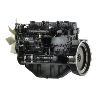
Check springs
for fatigue.
Check levers for
smooth movements.
Check shaft for flaws.
Check springs
for fatigue.
Check sliding sleeve joint
for wear and damage.
Check sliding
sleeve for wear,
damage and
smooth movement.
Check weight for
wear and damage.
Figure 108 Inspection governor system parts
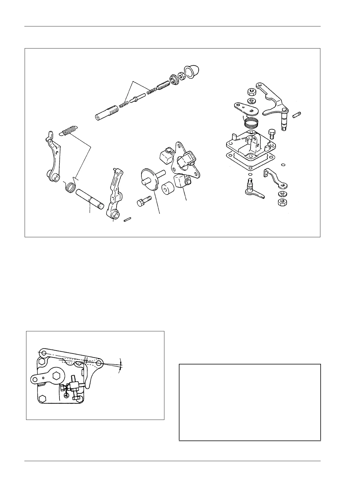
Figure 109 Installing speed control lever
5½ degrees
(Standard) No
play exceeding
5½ degrees
permitted
CAUTION
a. After press-fitting each grooved pin, check if the
shaft rotates smoothly.
b. Apply oil to the O-rings before installing them.
c. No deflection exceeding 20 mm [0.7874 in.] is
permitted for the governor spring installation.
d. Install the governor spring lever and speed
control lever so that play of angle between levers
(standard: 5½ degrees) is minimized.
 Loading...