22 / 155
Service Manual Mitsubishi L-Series diesel engines
Version 08/2004
ENGLISH
MAINTENANCE GENERAL
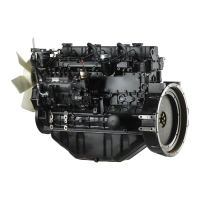
5.3 Adjusting the valve clearance
Procedure
1. Set the cylinder to be adjusted to the top dead
center of compression stroke.
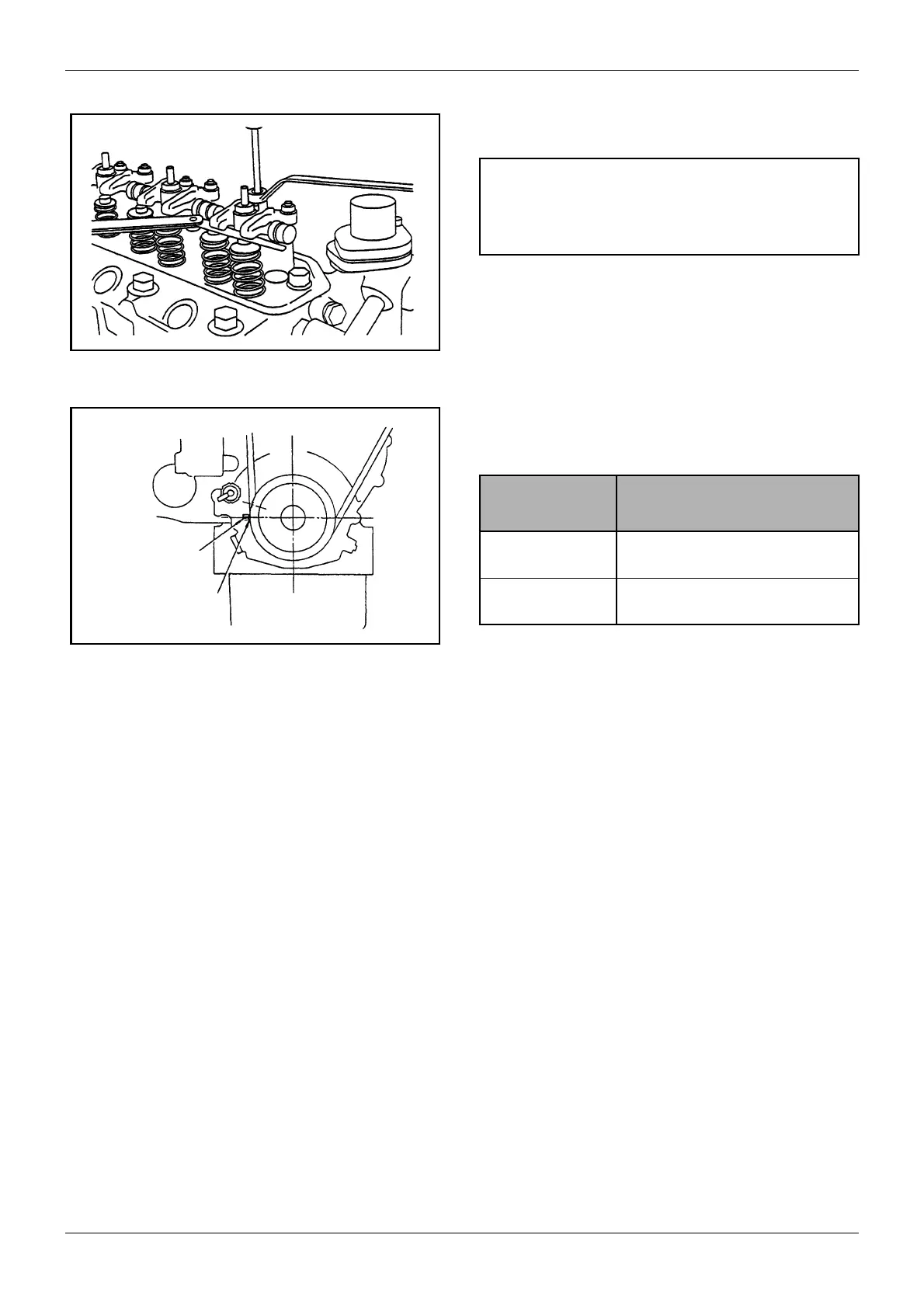
2. The top dead center of compression stroke can be
obtained by aligning the TDC (Top Dead Center)
mark (notch) on the crankshaft pulley with the
mark on the gear case.
3. First align the TDC mark for the No. 1 cylinder.
Confirm that the valves do not move up and down
when the crankshaft is turned about 20° in normal
direction of rotation and in reverse direction.
4. When setting the top dead center for the No. 2
cylinder and that for the No. 3 cylinder, perform as
follows:
a L2 (Two-cylinder engine)
Turn the crankshaft 180° clockwise from TDC
(Top Dead Center) of the No. 1 cylinder, to set
the No. 2 cylinder TDC.
b L3 (Three-cylinder engine)
Turn the crankshaft 240° clockwise from TDC
of the No. 2 cylinder, to set the No. 3 cylinder
TDC. Further, turn the crankshaft 240°
clockwise from No. 3 cylinder TDC and
reconfirm the position of the No. 2 cylinder
TDC.
Figure 10 Adjusting valve clearance
CAUTION
Be sure to retighten the cylinder head bolts before
adjusting the valve clearance.
Figure 11 Timing mark
TDC mark on
crankshaft pulley
Mark on
gear case
Tightening
torque
Unit: N·m (kgf·m) [lbf·ft]
M10 bolt 73.5 to 83.4 (7.5 to 8.5)
[54.25 to 61.48]
M8 bolt 19.6 to 29.4 (2.0 to 3.0)
[14.47 to 21.70]
Table 10 Tightening torque
 Loading...