Hardware Specifications10
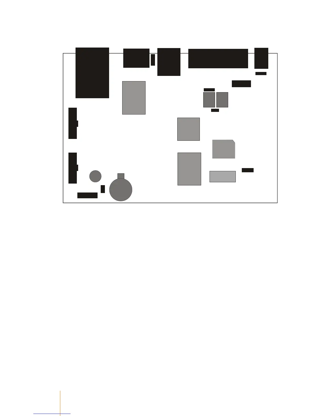
Location of Components
Ethernet
Aux
Main
Interface
P o w e r
D is p la y
K e y b o a rd
Card
R e la y
1
R e la y
2
Flash
JP15
JP15
JP12
JP6
JP22
Battery
JB1
C N 11
CN4
Hub
CPU
LAN
RAM
Beeper
Internal jumpers and connectors
The circuit designation of a jumper is usually ‘JP’ and a connector is ‘CN’, however due to an
historical screen printing error, some jumpers are labelled ‘CN’ and some connectors ‘JP’. They
have been left like this to minimise confusion between models.
Here is a list of useable jumpers and connectors:
Label Function
CN4 External card reader connector
CN11 Aux port voltage selector jumper
JB1 Input Jumper Block with 6 individual jumpers (A – F)
JP6 Vin Jumper
JP12 Relay earthing jumper
JP15 Relay 1 Normally open / Normally closed select jumper
JP22 Buzzer Enable jumper
JP64 12C BUS connector