Sec 1: 8-38 Disassembly/Reassembly Procedures: Radio Reassembly
8.9.1.10 Assemble Speaker Grille Assembly (A)
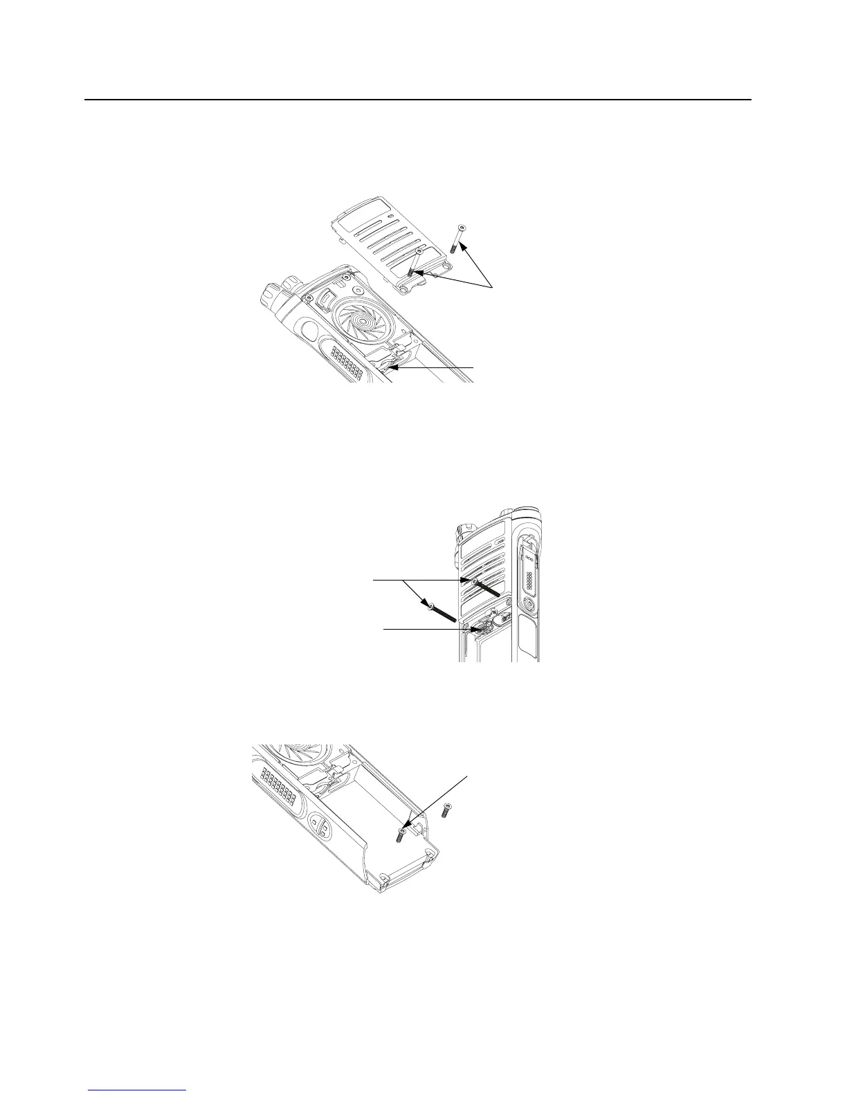
1. Install the Speaker Grille (A) by inserting the top lip under the control top bezel and rotating
the grille into place. See Figure 8-55.
Figure 8-55. Remove Center Screws
NOTE: Ensure the Memory Door (33) is in place and the memory door screw shaft is
aligned with the screw hole.
2. Insert the two center screws (29) and torque to 10 in-lbs. See Figure 8-56.
Figure 8-56. Insert Center Screws
3. If removed, insert the two bottom screws (30) into the screw holes at the bottom of the radio
as shown in Figure 8-57., and torque to 10 in-lbs.
Figure 8-57. Insert Bottom Screws
NOTE: Refer to the appropriate section in this manual for reinstalling the antenna, battery,
or any other accessory that was previously connected or attached to the radio prior
to servicing.
Center Screws (29)
Memory Door (33)
Center Screws (29)
Memory Door (33)
Bottom Screws (30)

 Loading...


