Disassembly/Reassembly Procedures: Radio Reassembly Sec 1: 8-37
NOTE: Avoid any lubricant to come in contact with any internal components.
2. Ensure the Seal is free from any debris or foreign material.
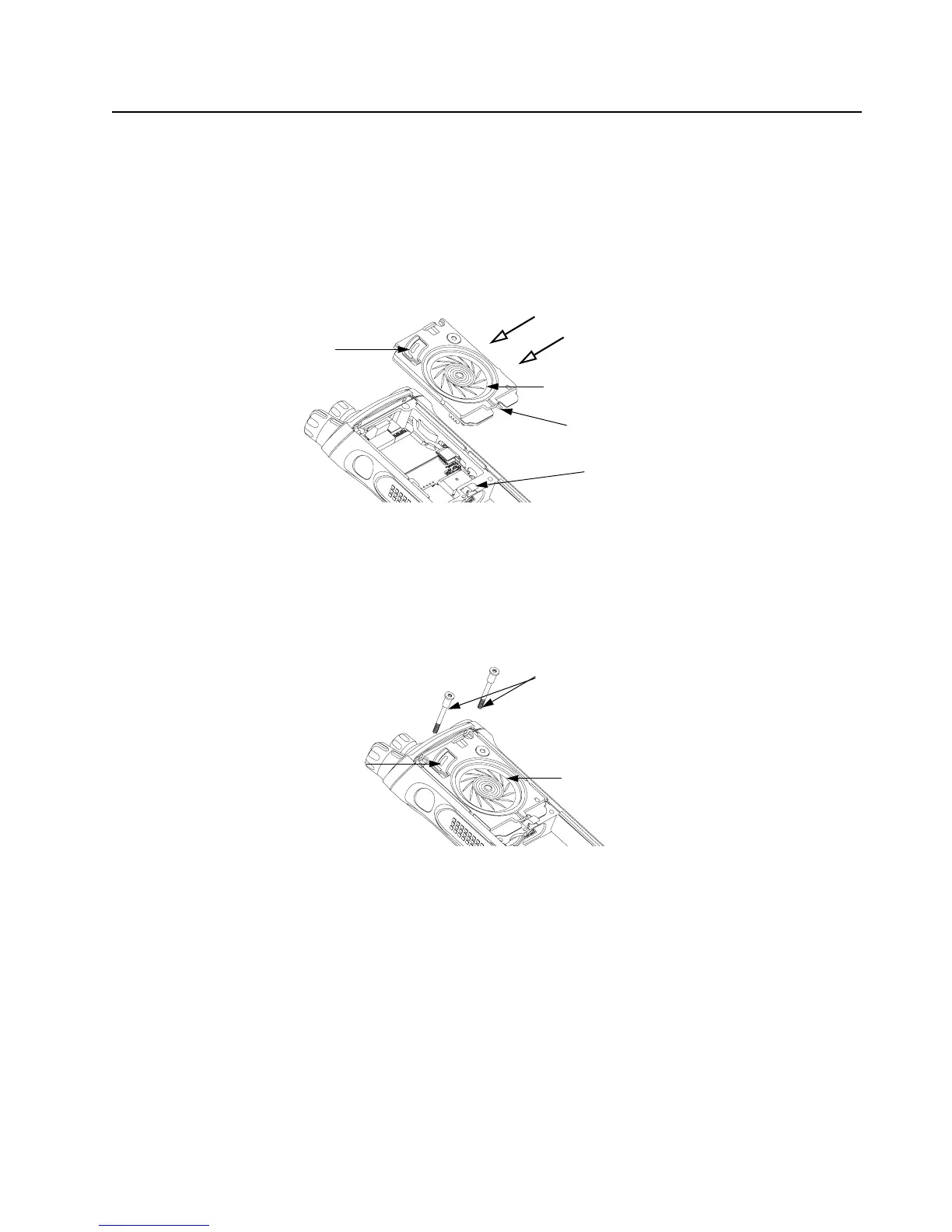
3. Align the Speaker Module's Pin feature located on the bottom edge directly below the
speaker, into the hole on the chassis hook feature.
4. Swing the Speaker Module down and firmly press the top side into the radio as shown in
Figure 8-53.
Figure 8-53. Insert Speaker Module
5. While holding the Speaker Module down, place the two top screws (28) into the their
respective holes and torque the screws to 10 in-lbs with an IP8 Torx Bit in a torque driver. See
Figure 8-54.
IMPORTANT: For proper sealing, Speaker Module (B) must be held down during the
torquing of the screws.
Figure 8-54. Insert Top Screws
Speaker Cone
Port Seal (25)
Pin Feature
Chassis Hook Feature
Top Screws (28)
Speaker Cone
Port Seal (25)

 Loading...


