SHOP MANUAL MT26/31 - 08.2006 SHOP MANUAL MT26/31 - 08.2006
SHOP MANUAL MT26/31 - 08.2006 SHOP MANUAL MT26/31 - 08.2006
TRANSMISSION
Ch 2 page 114 Ch 2 page 115
TRANSMISSION
TRANSMISSION
Ch 2 page 114 Ch 2 page 115
TRANSMISSION
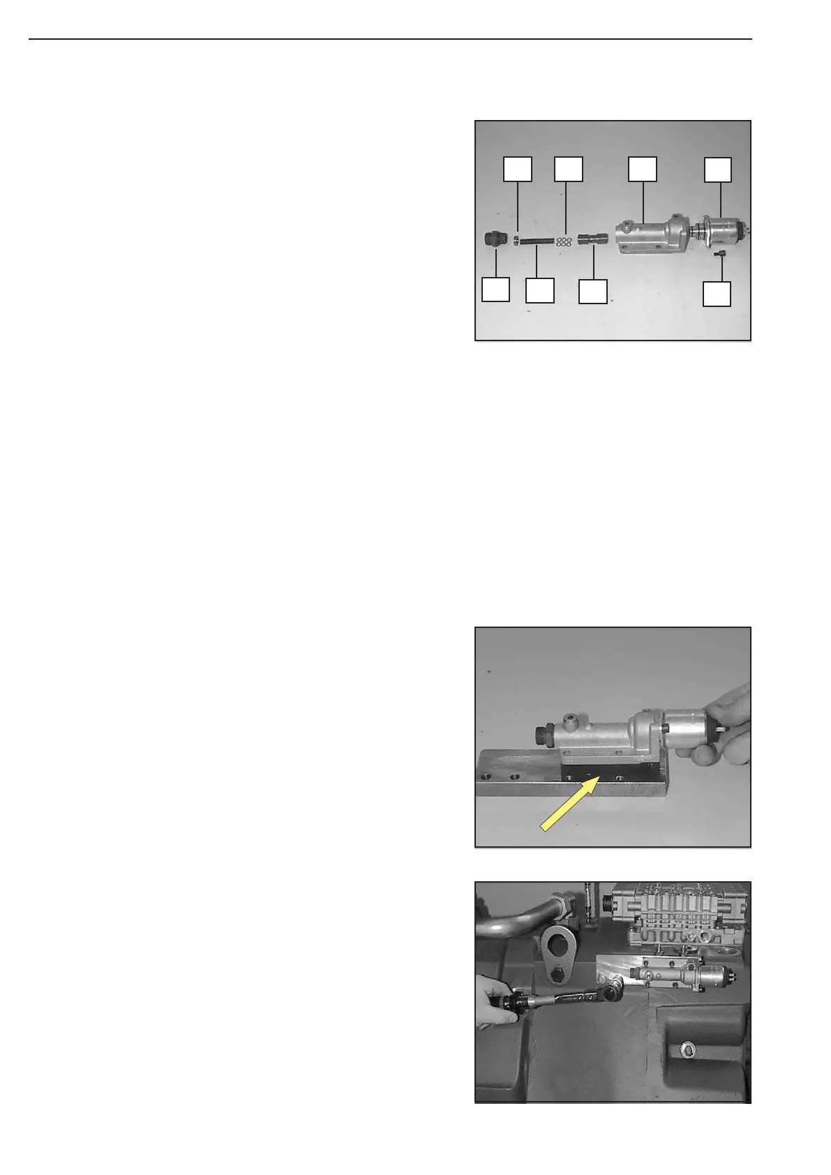
Install WK-Valve components according to the Figure on the left.
1 = Solenoid valve
2 = Socket head screw + Spring washer (2x)
3 = Selector housing
4 = Piston
5 = Shim rings (empirical value, 6 units/0,5 mm thick, each)
6 = Compression spring
7 = Stop (optional, empirical value A = 3,0 mm)
8 = Connecting fitting (install new O-ring)
With the shim rings 5 and the stop 7, the WK pressure 13
±1 bar
will be determined !
Install stop 7, with the stepped plane face facing the com-pression
spring !
Torque limit socket head screws (M5/8.8) .... 5,5 Nm
Mount gasket (Arrow) and fasten selector housing by
means of socket head screws (mount flat washers).
Torque limit (M6/8.8) .................................. 9,5 Nm
Fasten WK-valve on the gearbox housing, using hex. head
screws.
Torque limit (M8/8.8) .................................. 23 Nm
Figure 46
Figure 45
Figure 44
1
3
4
2
5
6
7
8