SHOP MANUAL MT26/31 - 08.2006 SHOP MANUAL MT26/31 - 08.2006
SHOP MANUAL MT26/31 - 08.2006 SHOP MANUAL MT26/31 - 08.2006
TRANSMISSION
Ch 2 page 196 Ch 2 page 197
TRANSMISSION
TRANSMISSION
Ch 2 page 196 Ch 2 page 197
TRANSMISSION
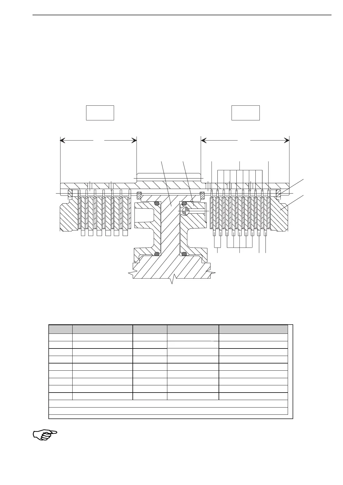
The following sketch or table show plate stacking and installation position of the components!
Outer plates Item 3 with the uncoated side facing the piston or the end shim!
The respective clutch side can be recognized by the length of the plate carrier, see sketch!
K3 = Measure Y (long plate carrier side)
K4 = Measure X (short plate carrier side)
Item.
Designation
Quantity
s (mm)
Remark
1 Plate carrier 1
2 Piston 1
3 Outer plate 2 1,85 One-,side coated
4 Outer plate 8 2,5 Coated on both sides
5 Inner plate 3 2,5
6 Inner plate 5 3,0
7 Inner plate 1 2,5 ... 4,0 Optional
8 Snap ring 1 2,55 ... 3,10 Optional
9 En
d
1
Number of friction surfaces: 18
Plate clearance: 2,6 ... 2,8 mm
shims
Figure 259
Multi-disc clutch-K3