SHOP MANUAL MT26/31 - 08.2006 SHOP MANUAL MT26/31 - 08.2006
SHOP MANUAL MT26/31 - 08.2006 SHOP MANUAL MT26/31 - 08.2006
TRANSMISSION
Ch 2 page 114 Ch 2 page 115
TRANSMISSION
TRANSMISSION
Ch 2 page 114 Ch 2 page 115
TRANSMISSION
Retarder
Function of a retarder
(Schematic view)
General:
The hydrodynamic Retarder (fluid brake), installed upon request, is arranged between engine
and torque converter thus achieving a good braking effect in all gears.
The Retarder is a wear-free, gear-depending acting hydrodynamic-brake.
The application of the Retarder is therefore especially to recommend at longer downgrade
drives or to brake down out of high driving speeds, because in this way, the service brake will
be saved and in an emergency case, the full braking effect (no fading) of the service brake will
be disponible.
This is the case of a so-called primary retarder, i.e. it is positively engaged with the engine.
Therefore, in the lower gear, higher braking moments can be achieved then in the correspon-ding
higher gears.
Because of this fact, it is necessary that the installed WK must be closed, so that the full retarder
moment can become effective.
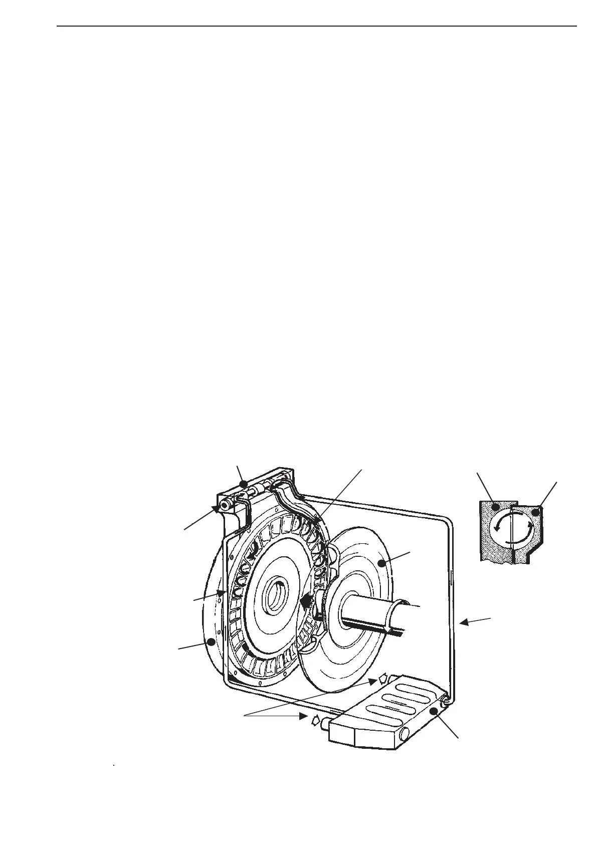
Layout and Function of the Retarder:
The Retarder in its functional components (see Draft) is composed of the Rotor, the Stator and
the Control device. The Rotor (the rotating part of the retarder) is driven from the overrunning
vehicle via axle, universal shaft, transmission and shift clutch.
The two-piece stator is composed of the stator itself, which is rigidly connected with the gear-box
housing and the stator ring. This stator ring is a vane ring which is arranged between rotor
and stationary stator, and serves to reduce the idling losses.
The control device is a valve block which is controlled by means of compressed air.
In shut off condition, i.e. without oil filling, the stator ring will be hold in a position by spring
force by which bypass ducts between rotor and stator impellers will be created.
In the retarder mode, i.e. with oil filling, the stator ring will be displaced by the circulating oil
by exceeding the spring forces up to a stop.
In this position, it is creating together with the stationary part of the stator a closed impeller
ring „counter-rotating“, to the rotor.
Rotor
Retarder valve
Discharge spiral
Stator
Rotor
Connection to
the heat
exchange
r
Control-air
connection
Connection
from the heat
exchanger
Stator
Cooling
water
Heat exchanger