SHOP MANUAL MT26/31 - 08.2006 SHOP MANUAL MT26/31 - 08.2006
SHOP MANUAL MT26/31 - 08.2006 SHOP MANUAL MT26/31 - 08.2006
TRANSMISSION
Ch 2 page 250 Ch 2 page 251
TRANSMISSION
TRANSMISSION
Ch 2 page 250 Ch 2 page 251
TRANSMISSION
See: (in this chapter)
- Electro hydr. shift control valve, cross section
- Clutch chart
- Oil circuit diagram
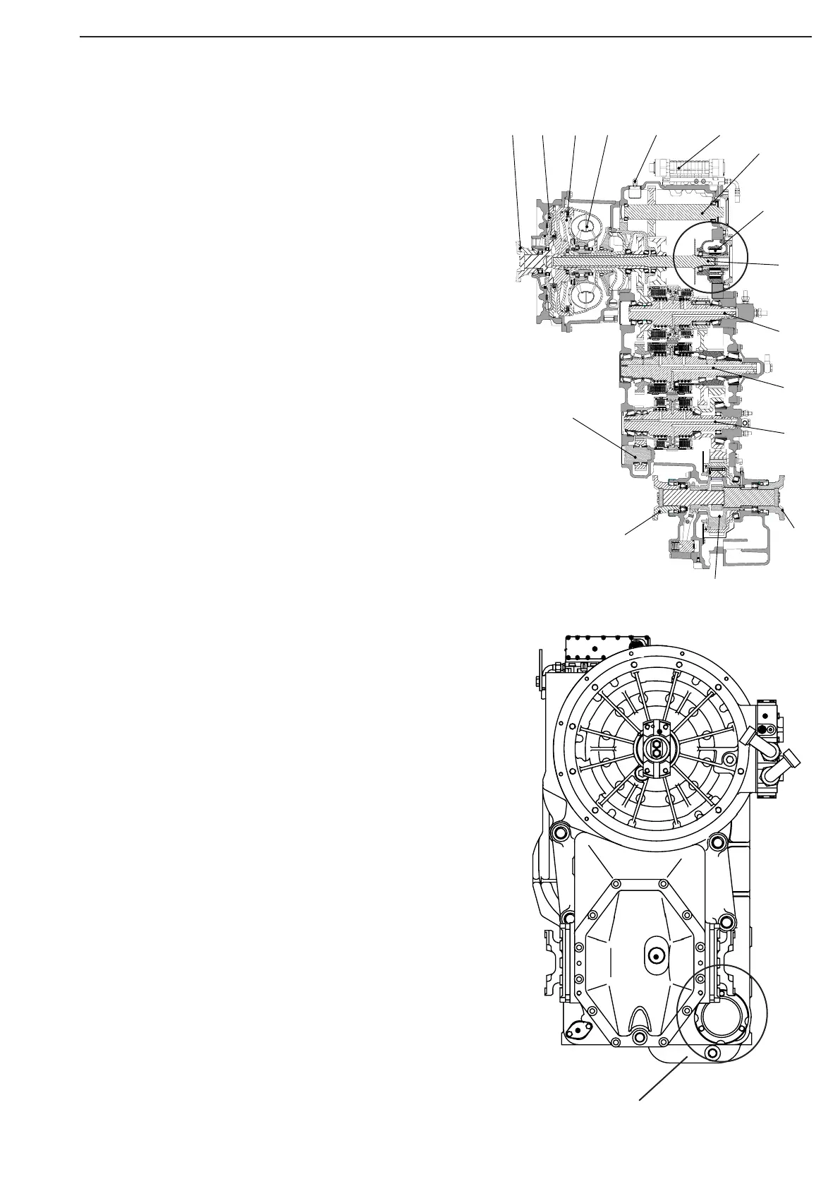
The transmission pump, necessary for the oil supply of the
converter, and for the transmission control, is located in
the transmission on the engine-dependent input shaft.
See figure item 8.
The feed rate of the pump is:
Q = 115 l /min, at nEngine = 2000 min
-1 .
This pump is sucking the oil via the coarse filter out of the
oil sump and delivers it via the Fine filter – the filter is fit-
ted externally from the transmission – to the main pressure
valve.
If because of contamination, resp. damage,
the through-flow through the Fine filter is
not ensured, the oil will be directly
conducted via a filter differential pressure
valve (bypass valve .p =5,7 bar) to the
lubrication.
In this case, an error indication is shown
in cab on the Display.
Transmission control. The pump
Coarse filter
Transmission
view from front