Subject to modifications
User Manual
Operation Instructions
2.1A-30008-A04
Page 15 of 48
LINCOLN GmbH & Co. KG • Postfach 1263 • D-69183 Walldorf • Tel +49 (6227) 33-0 • Fax +49 (6227) 33-259
Mode of Operation, continuation
Setting of adjustable pump elements, continuation
Retrofit adjustment of max. lubricant output
6001a02
NOTE
In order to ensure that the lubricant out-
put setting will be as exact as possible,
first the actual dimensions “S” of the
max. lubricant output must be ascer-
tained as follows. The measured differ-
ence from the nominal value 29 must be
considered for all other settings values
(e.g. ± 0.1).
Unscrew the adjusting spindle (pos.1
1)
) from the pump
element body (pos.3) until “S” is approx. 30 mm.
Screw counter nut (Pos.2) onto stop collar of the adjusting
spindle (pos.1).
Screw adjusting spindle (pos.1) with counter nut (pos.2)
into pump element body (pos.3) until stop.
1)
All indications of positions refer to fig. 14, page 14.
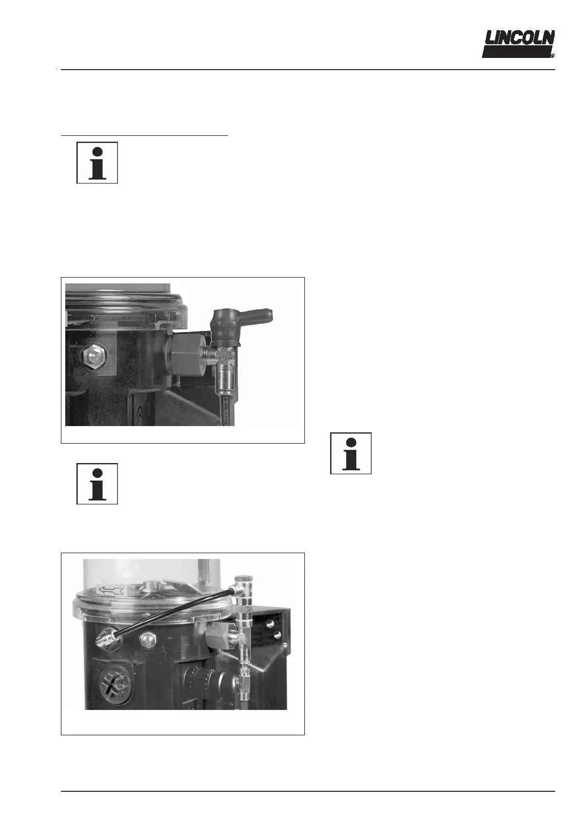
Pressure Relief Valve
10022618a
Fig. 16 Pressure relief valve
6001a02
IMPORTANT
Each pump element must be secured
with a pressure-limiting valve.
The pressure relief valve is not contained
in the scope of supply of the pumps 223,
233. Therefore it is to be ordered sepa-
rately (see Spare Parts Catalogue).
without grease return
The pressure relief valve
- limits the pressure build-up in the system.
- opens, if the specific overpressure is reached.
- is to be selected according to the requirements to the
lubrication plant (see different opening pressures; 200,
270, 350 bar).
If lubricant is leaking at the pressure relief valve, this indi-
cates that the system is malfunctioning.
Despite existing fault monitoring devices a regular visual
and function control must be carried out on the lubrication
system.
6001a02
NOTE
Between a malfunction (blockage) and the
following fault indication (lubricant leak-
age; monitoring intermittent LED display)
there may be a longer time delay.
The duration of the delay depends on the
type and length of the lines, the type of
lubricant, the ambient temperature and
other influences.
6336b04
Fig. 17 Pressure relief valve with grease return
with grease return (optional)
If the system is blocked, grease will leak from the pres-
sure relief valve. This grease quantity is returned to the
reservoir.