Subject to modifications
User Manual
Operation Instructions
2.1A-30008-A04
Page 21 of 48
LINCOLN GmbH & Co. KG • Postfach 1263 • D-69183 Walldorf • Tel +49 (6227) 33-0 • Fax +49 (6227) 33-259
Mode of Operation, continuation
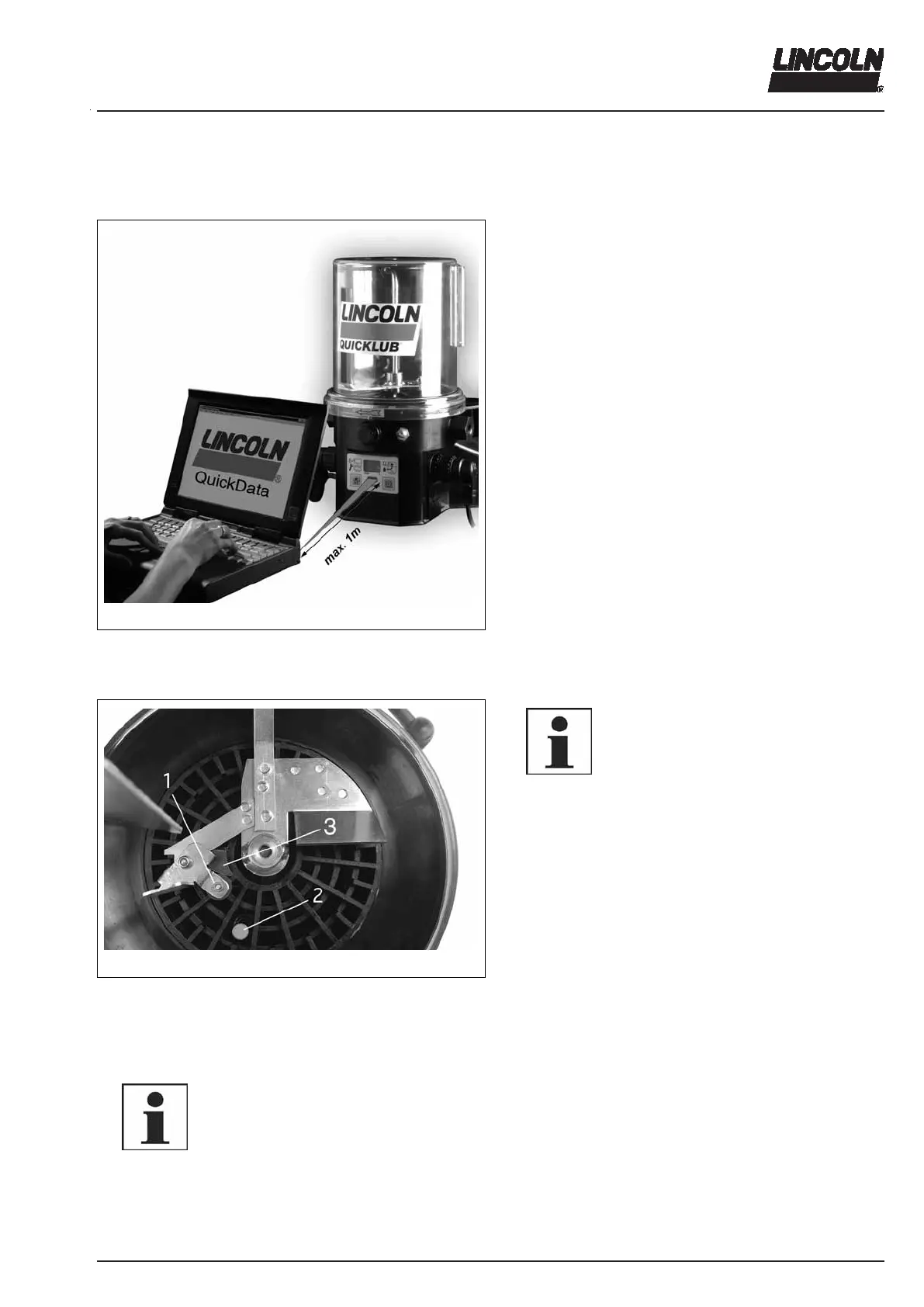
Reading of the data memory “QuickData“ (only P 233)
4359a01
Fig. 34 Reading of the data memory
Read data memory via a suitable laptop with integrated
or, if not available, external infrared interface (see User
Manual “Diagnostic Software QuickData“.
To be able to read from the reading window, place the
infrared interface of the laptop at a maximum distance of
1 m horizontally in front of it, and then read the data.
Hardware requirements
Operating system: ...MS Windows 95, 98, ME, NT, 2000
- Computer: ......................IBM AT or compatible device,
- 486 DX or faster,
- 16 MB RAM hard disk with min. 1 MB free memory
- a free serial connection (COM-Port, .................9-pole)
- mouse
- CD-ROM drive
External infrared interface
- Part n°. 236-10127-1
- Protocol : IrDA 1.2 19200/8/N Baud
- Plug-in for COM-Port (RS 232, 9-pole SubD-plug;
socket)
- Reach approx. 1 m
Low-level control for grease
00002444
Fig. 35 Switching parts of the low-level control
1 - Guiding plate with round
solenoid (at the stirring
paddle)
2 - Electromagnetic switch
3 - Control cam
6001a02
NOTE
The above-mentioned switching parts
must not be used with fluid grease. In
this case, use a float magnetic switch;
see below low-level control for oil.
6001a02
NOTE
The flashing signal starts only after the
solenoid has activated the electromag-
netic switch 6 times contact-free.
When the reservoir is filled
The stirring paddle rotates clockwise during the operating
time.
Due to the rotating motion of the stirring paddle in the
lubricant the pivoting guiding plate with the round sole-
noid, item 1
1)
, is pressed backwards. The solenoid moves
toward the center of rotation of the stirring paddle. The
electromagnetic switch item 2
1)
cannot be activated.
Control cam item 3
1)
guides the round solenoid with the
pivoting guiding plate automatically outwards, in the direc-
tion of the reservoir wall. After the lubricant has left the
control cam, it flows against the guiding plate, thus dis-
placing the solenoid again onto the center of rotation of
the stirring paddle.
1)
All indications of positions refer to fig. 35.