Subject to modifications
User Manual
Operation Instructions
2.1A-30008-A04
Page 9 of 48
LINCOLN GmbH & Co. KG • Postfach 1263 • D-69183 Walldorf • Tel +49 (6227) 33-0 • Fax +49 (6227) 33-259
Description
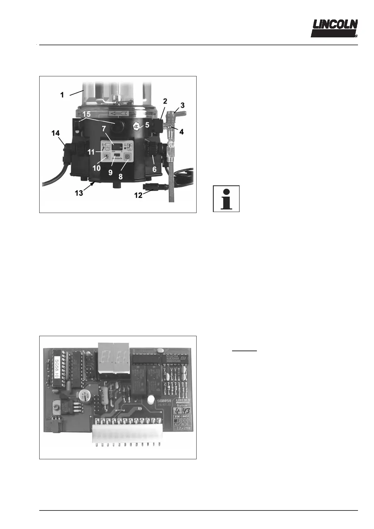
4355a01
Fig. 2 Components of pump 223, 233
1 - Reservoir
2 - Pump element
3 - Pressure relief valve
4 - Filling nipple, system
emergency lubrication
possible
5 - Fillilng nipple, pump
6 - Adaptor for piston detec-
tor
7 - Display
8 - Momentary-contact
switch for indication or
setting of pause time
9 - Reading window for Datalog-
ger (only P233)
10 - Momentary-contact switch for
additional lubrication
11 - Membrane key pad
12 - Piston detector
13 - Covering to the p.c.b.
14 - Adaptor for power supply
15 - Closure plug for the use of a
pump element
Quicklub centralized lubrication pumps
Are compact multi-line pumps consisting of the following
components:
- Housing with integrated motor
- Reservoir with stirring paddle and fixed paddle
- P223: Control printed circuit board (p.c.b.)
P233: Data logger (control p.c.b. with readable
data memory)
- Pump element
- Accessories:
- Pressure relief valve
- Refilling unit
- Electrical connection parts
6001a02
NOTE
Pressure relief valve are not part of the
pump components and have to be or-
dered separately. Accessories for refilling
of the reservoir (see parts catalogue).
can drive up to 3 pump elements
operate according to lubrication cycles (pause and operat-
ing times)
can be equipped with a low-level control
can supply up to 100 lubrication points depending on the
line lengths
are designed for the automatic lubrication of the con-
nected lubrication points
are designed for the delivery of greases up to NLGI 2 at
temperatures from - 25° C to 70° C
can be used at low temperatures down to - 40° C
During the operating time the pump dispenses lubricant to the
connected lubrication points via one or several metering de-
vices.
6288b04
Fig. 3 Control p.c.b. MF00 (P223)
P223 without data logger
Control p.c.b. MF00
The control unit is installed in the housing of the pump
behind the membrane keypad (see pos. 11, fig. 2) as an
integrated p.c.b. MF00.