SHOP MANUAL MT26/31 - 08.2006 SHOP MANUAL MT26/31 - 08.2006
SHOP MANUAL MT26/31 - 08.2006 SHOP MANUAL MT26/31 - 08.2006
TRANSMISSION
Ch 2 page 258 Ch 2 page 259
TRANSMISSION
TRANSMISSION
Ch 2 page 258 Ch 2 page 259
TRANSMISSION
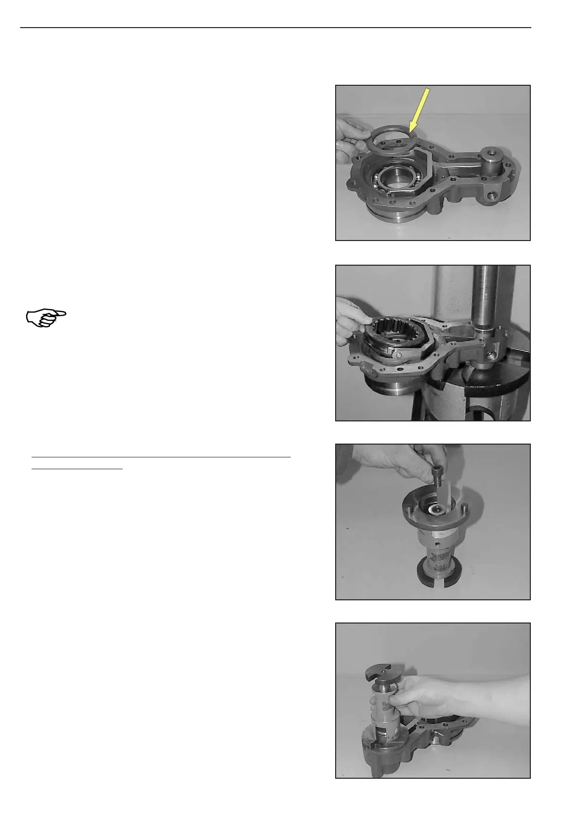
Figure 464
Figure 467
Figure 466
Figure 465
Insert disc with chamfer (arrow) showing upwards
Line up measuring device and position it on the mounting face
until contact is obtained.
(S) Measuring device 504179
Adjust shifting travel by means of measuring device (S)
(Figure 466 ... 470):
Insert stop screw into the measuring device.
(S) Measuring device 504179
Pre-load compression spring, install sliding blocks and sliding
sleeve.
Observe the installation position of the slid
-
ing sleeve – the large chamfer at the outer
diameter showing downwards!