SHOP MANUAL MT26/31 - 08.2006 SHOP MANUAL MT26/31 - 08.2006
SHOP MANUAL MT26/31 - 08.2006 SHOP MANUAL MT26/31 - 08.2006
TRANSMISSION
Ch 2 page 262 Ch 2 page 263
TRANSMISSION
TRANSMISSION
Ch 2 page 262 Ch 2 page 263
TRANSMISSION
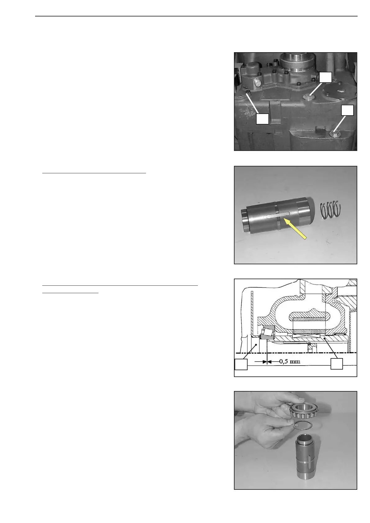
Figure 483
Figure 486
Figure 485
Figure 484
Provide screw plugs ( 1 and 2 ) with new O-ring and install
them.
Mount gasket and fasten cover plate (3) by means of hex. head
screws.
Torque limit (screw plug) .......................... M
A
= 140 Nm
Torque limit (M8/8.8) .............................. M
A
= 23 Nm
Line up disc s = 1,90 mm and position bearing inner race until
contact is obtained.
Adjust gap dimension = 0,50 mm (Driver/input shaft
(Figure 485 ... 489):
1 = Driver
2 = Input shaft
Input shaft (power take-off – pump)
Tilt gearbox housing by 180°.
Squeeze V-rings (3x) into the recess of the driver (internal
splines).
Install fitting key (arrow).
1
3
2
1
2