SHOP MANUAL MT26/31 - 08.2006 SHOP MANUAL MT26/31 - 08.2006
SHOP MANUAL MT26/31 - 08.2006 SHOP MANUAL MT26/31 - 08.2006
TRANSMISSION
Ch 2 page 278 Ch 2 page 279
TRANSMISSION
TRANSMISSION
Ch 2 page 278 Ch 2 page 279
TRANSMISSION
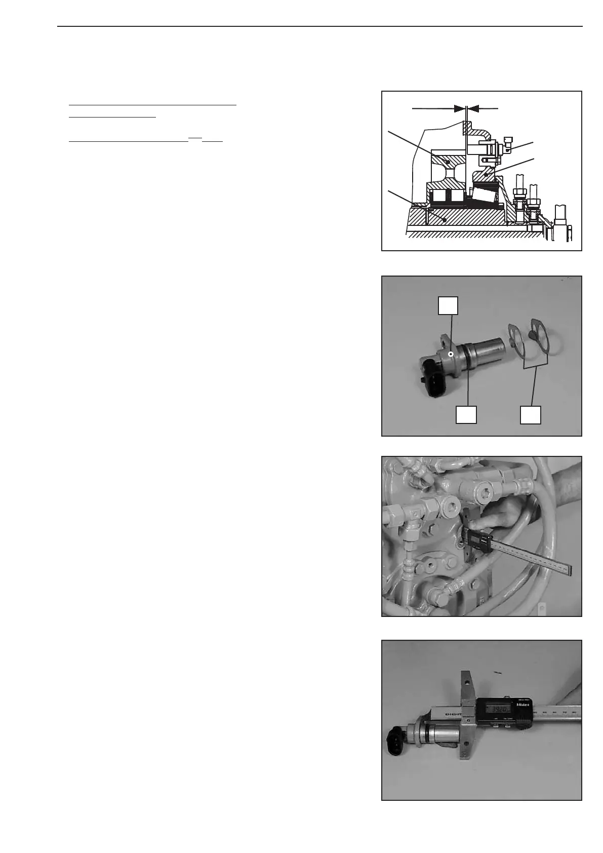
Figure 543
Install speed sensor n-output (31),
Figure 540 ... 545:
Setting measure X = 1,0
+ 0,5
mm
See also chapter 2.2 ,Testing & Adjusting
Determine measure II from the contact face to the mounting
face.
Measure II e.g. ................................... 39,00 mm
(S) Digital-depth gauge 504175
Determine measure I from the housing face to the spur gear
K3.
Measure I e.g.. ...................................... 39.20 mm
The figure on the left shows the speed sensor (Hall sensor)
1 = Speed sensor
2 = O-ring
3 = Setting plate(s)
Figure 540
Figure 542
Figure 541
1
3
2