SHOP MANUAL MT26/31 - 12.2004SHOP MANUAL MT26/31 - 12.2004
DRIVE LINE
CH 3 PAGE 6
SHOP MANUAL MT26/31 - 12.2004SHOP MANUAL MT26/31 - 12.2004
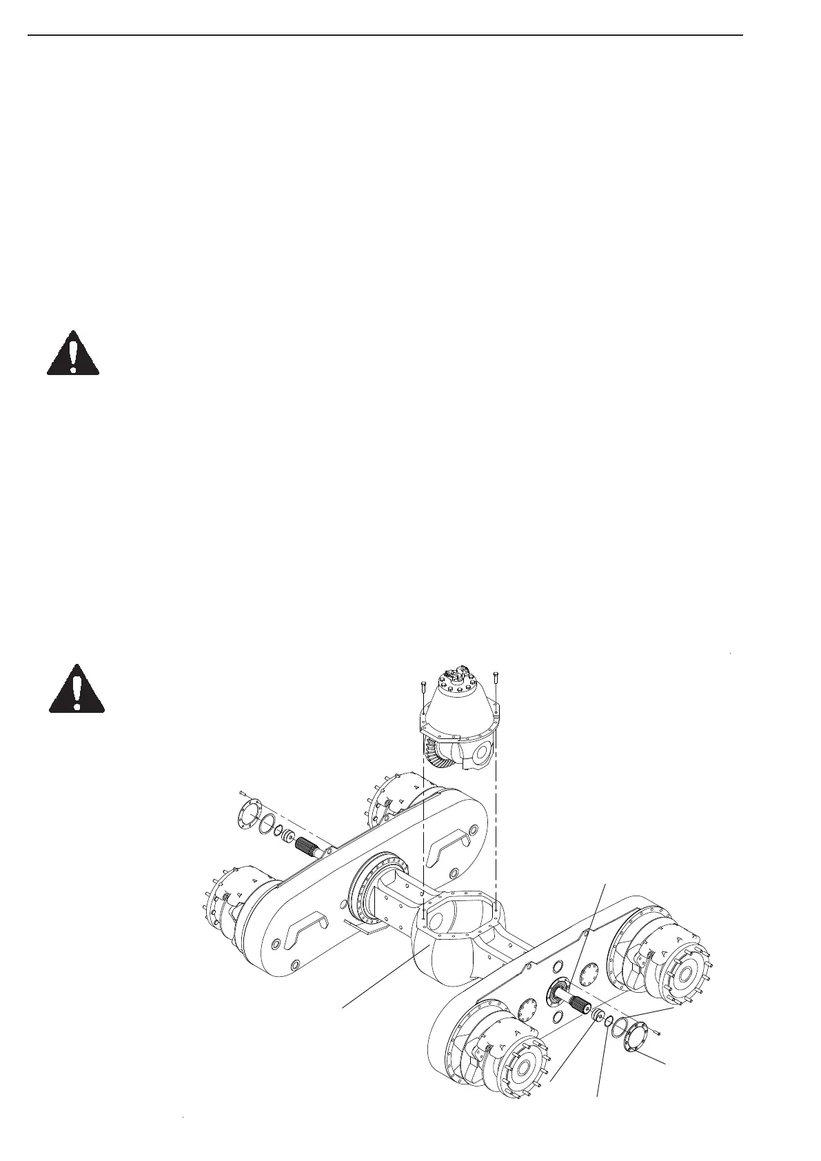
Rear Axle
Housing
Seal Plug
Circlip
Shim
Pinion
Cover
Drive Shaft
Rear Axle
Differential
Fig 3.6 Rear Axle Differential
3.3.2 Rear Axle Differential
The Rear Axle Differential distributes the power between left and right rear wheel tandem housing.
Removal
Remove rear axle unit from dumper (Ref 3.3.1)
Release eight bolts, and remove pinion cover. Save the shims behind.
Remove circlip inside pinion, and withdraw seal plug, using a slide hammer equipped with an M16
adapter.
Withdraw drive shaft to disengage the differential, by using slide hammer equipped with an M16 adapter.
Pull shaft approx. 200 mm out. Repeat procedure on drive shaft on oposit side.
Rotate the rear axle housing until the differential input flange is in an upright position.
Support the rear axle housing from rotating by use of a floor jack.
Unscrew the 16 bolts securing the differential unit to the rear axle hosing.
Take note of where the different length of bolts are located.
Fasten a lifting device to the differential input flange, and lift the unit out of the housing.
WARNING!__________________________________________
Be aware of the risk of injury to people and equipment when
handling heavy objects!
Clean the rear axle housing mating flanges.
Installation
Apply a coat of sealing compound to the axle housing mating flange.
Lift the differential housing, and lower carefully into the rear axle hosing.
Enter the 16 bolts, with each length in the right locations.
Tighten the 16 bolts, advancing in a star pattern.
Push drive shafts back into position.
Rotate the differential input flange slightly from side to side to engage the differential, and the pinion.
Replace thrust washers and circlips, and replace pinion cover and shims as removed.
Rotate rear axle unit back into normal position with input axle horisontal.
Replace rear axle unit. (Ref.3.3.1)
Control
Check that all parts are located as when removed, and that the assembly can be rolled without binding.
WARNING!____________________________
If ground is not level, necessary precations
to keep drive assembly from rolling out of
control must be taken to avoid injurys
to people and equipment.
Replace the rear axle drive
assembly on dumper.
(Ref. 3.3.1)