10
Serial Interface application
Switching sections and transferring target rates via ASD
72 30302710-02-EN V7.20141016
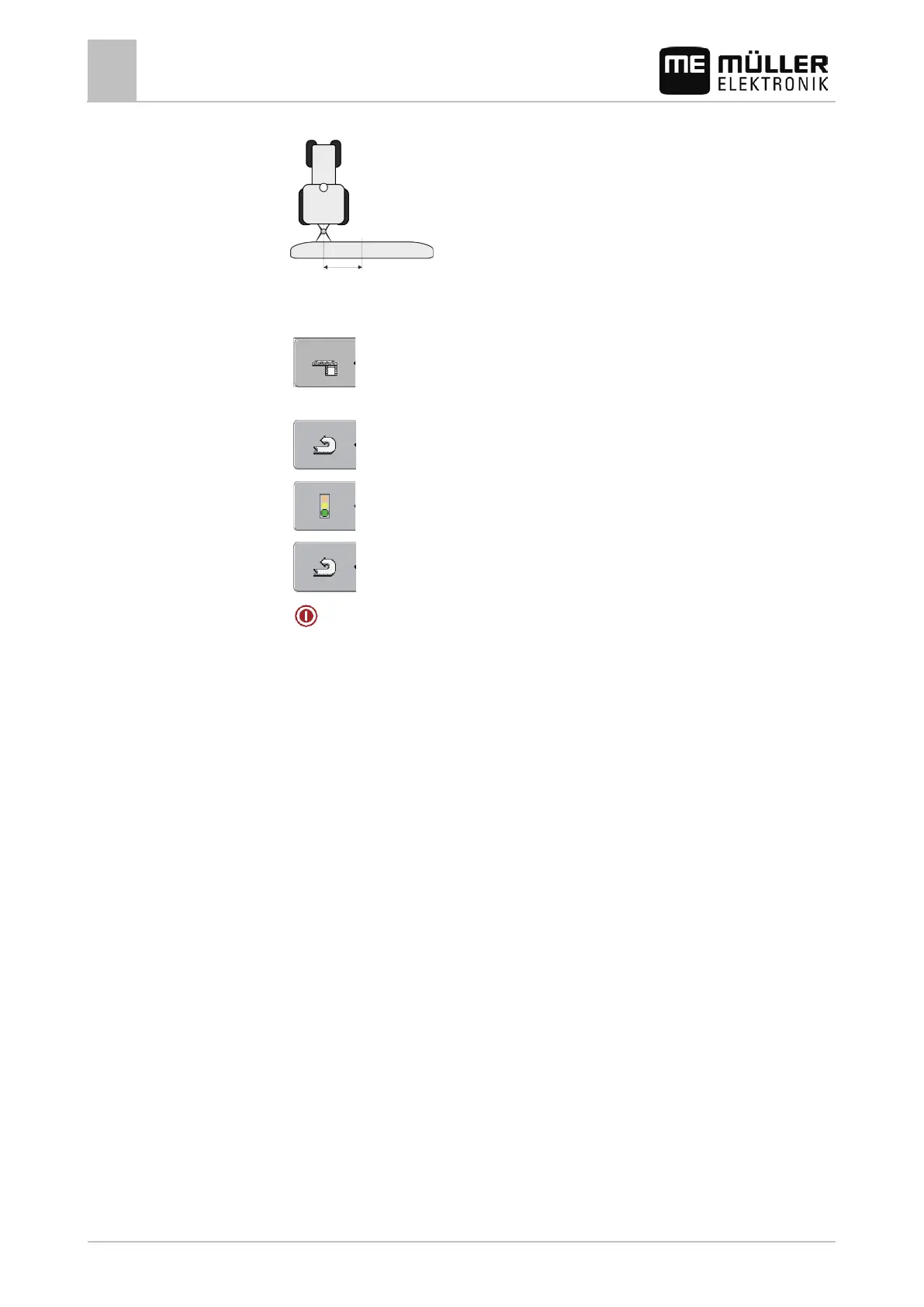
right, enter a positive value, and for a shift to the left, enter a negative value.
12. "Working Width" - The working width set in the on-board integrated display/controller.
13. "No. of sections" - The number of sections set in the on-board integrated display/controller.
14.
- The width of the individual sections set in the on-board integrated
display/controller.
15.
- Back.
16.
- Activate the implement profile.
17.
- Press and confirm to save the implement profile.
18.
- Restart terminal.
Further steps
You have set up the serial interface. You must now configure the applications of the terminal.
In the TRACK-Leader application:
1. Activate the "SECTION-Control" parameter under "Settings / General".
2. Configure the section switching in "Settings/ SECTION-Control".
3. Load a prescription map.
You can load the prescription map in two ways:
▪ As a shp file, in the TRACK-Leader application.
▪ As part of a ISO-XML task, if you are using the ISOBUS-TC application and a FMIS.
For more information, please refer to the TRACK-Leader and ISOBUS-TC operating instructions.
 Loading...