HARDWARE FUNCTIONAL TESTING 7. TESTING
7-6
7.2.6
DIGITAL INPUTS
AND TRIP COIL SUPERVISION
The digital inputs and trip coil supervision can be verified easily with a simple switch or pushbutton. Verify the SWITCH +24Vdc with a volt-
meter. Perform the steps below to verify functionality of the digital inputs.
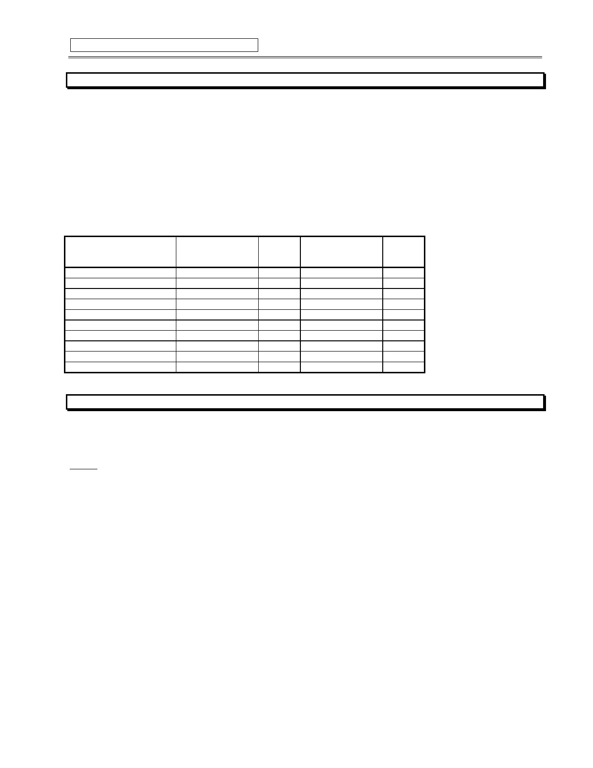
1. Open switches of all of the digital inputs and the trip coil supervision circuit.
2. View the status of the digital inputs and trip coil supervision in:
ACTUAL VALUES A1:\STATUS\DIGITAL INPUTS
3. Close switches of all of the digital inputs and the trip coil supervision circuit.
4. View the status of the digital inputs and trip coil supervision in:
ACTUAL VALUES A1:\STATUS\DIGITAL INPUTS
Table 7-10 DIGITAL INPUTS
INPUT EXPECTED
STATUS
(SWITCH OPEN)
4 PASS
8 FAIL
EXPECTED
STATUS
(SWITCH CLOSED)
4 PASS
8 FAIL
ACCESS Open Shorted
TEST Open Shorted
STARTER STATUS Open Shorted
EMERGENCY RESTART Open Shorted
REMOTE RESET Open Shorted
ASSIGNABLE INPUT 1 Open Shorted
ASSIGNABLE INPUT 2 Open Shorted
ASSIGNABLE INPUT 3 Open Shorted
ASSIGNABLE INPUT 4 Open Shorted
TRIP COIL SUPERVISION No Coil Coil
7.2.7
ANALOG INPUTS AND OUTPUTS
The SR469 specification for analog input and analog output accuracy is ±1% of full scale. Perform the steps below to verify accuracy. Verify
the Analog Input +24Vdc with a voltmeter.
4-20mA
1. alter the following setpoints:
SETPOINT S12:ANALOG I/O\ANALOG INPUT1\ANALOG INPUT1: 4-20 mA
SETPOINT S12:ANALOG I/O\ANALOG INPUT1\ANALOG INPUT1 MINIMUM:0
SETPOINT S12:ANALOG I/O\ANALOG INPUT1\ANALOG INPUT1 MAXIMUM:1000
(repeat for analog inputs 2-4)
2. Analog output values should be ±0.2mA on the ammeter. Measured analog input values should be ±10 units. Force the analog outputs
using the following setpoints:
SETPOINT S13:TESTING\TEST ANALOG OUTPUT\FORCE ANALOG OUTPUTS FUNCTION: Enabled
SETPOINT S13:TESTING\TEST ANALOG OUTPUT\ANALOG OUTPUT 1 FORCED VALUE: 0 %
(enter desired percent, repeat for analog outputs 2-4)
3. Verify the ammeter readings as well as the measured analog input readings. For the purposes of testing, the analog input is fed in from
the analog output (see Figure 7-1). View the measured values in:
ACTUAL VALUES A2:\METERING DATA\ANALOG INPUTS